9-179
P0500, P1500
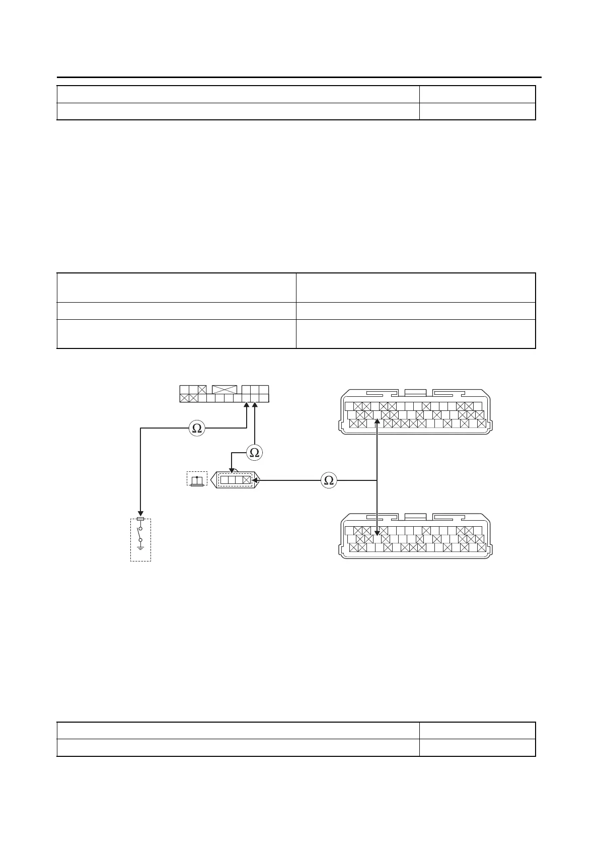
10.Wire harness continuity.
• Disconnect the relay unit coupler “1”, ECU coupler “2” and neutral switch coupler “3”.
• Remove the joint coupler cap “4”.
• Open circuit check
When the transmission is in neutral ON
When the transmission is in gear with the clutch lever released OFF
Is it correct indication?
YES
→ Go to step 21.
NO
→ Go to step 10.
Between relay unit coupler “1” and joint coupler
“4”
black–black/yellow
Between joint coupler “4” and ECU coupler “2” black/yellow–black/yellow
Between relay unit coupler “1” and neutral
switch coupler “3”
sky blue–sky blue
Gy
LLVP
P/WLg/LO/WY/LL/B
B/LB/LBr/WGy/GG/LBr/LB/YL/W
W/YW/GG/WG/WLg/BL/WL/Y
Gy
LLVP
P/WLg/LY/LL/B
B/LB/LBr/WGy/GG/LB/YL/W
W/YW/GG/WG/WL/WL/Y
2
**
2
*
1
3
4
B/Y
B
B/Y
W
L/W
R
L/B
LB
Sb/W
Sb
W
Br
L/W
RR
*. MTN890
**. MTN890D
Is resistance 0 Ω?
YES
→ Go to “Short circuit check”.
NO
a. Replace the wire harness.
b. Execute the diagnostic mode. (Code 21)
When the transmission is in neutral ON
When the transmission is in gear with the clutch lever released OFF