9-210
P0657
3. Connection of ECU coupler.
• Check the locking condition of the coupler.
• Disconnect the coupler and check the pins (bent or broken terminals and locking condition of the
pins).
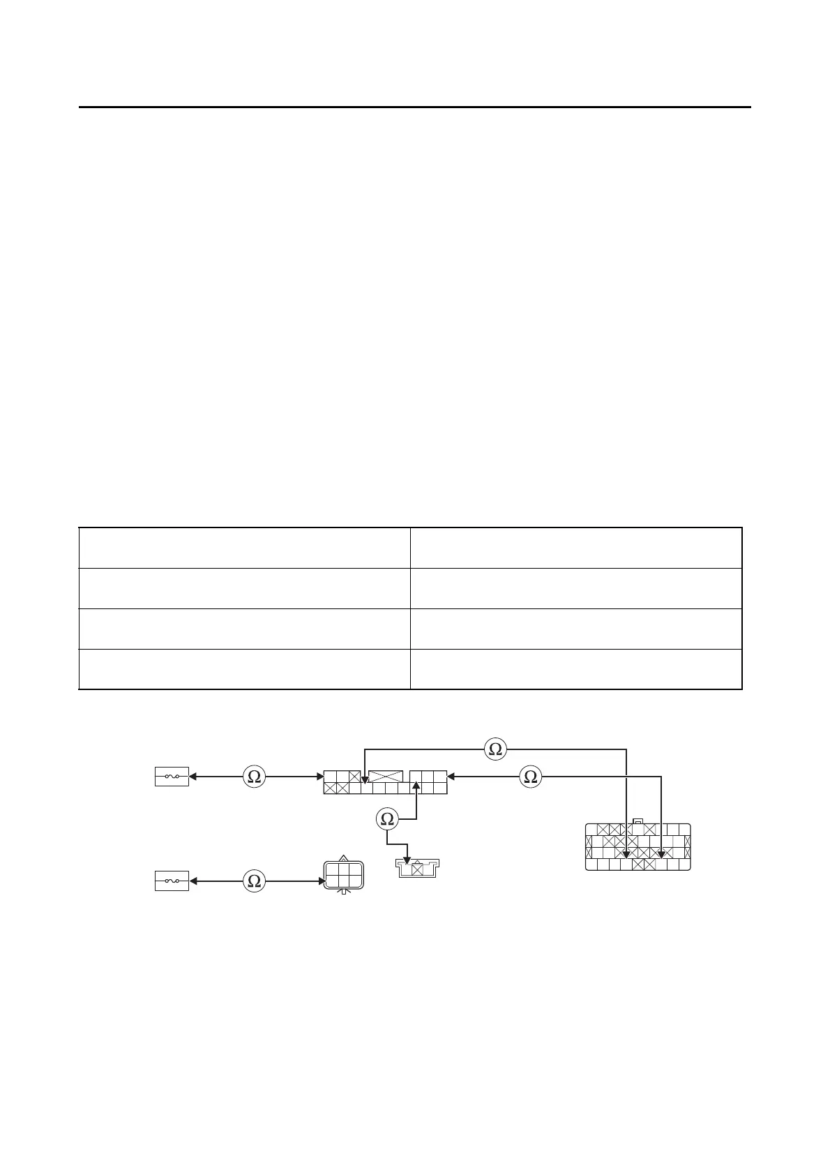
4. Wire harness continuity.
• Disconnect the fuel injection system fuse “1”, relay unit coupler “2”, ignition fuse 1 “3”, handlebar
switch (right) coupler “4” and ECU coupler “5”.
• Open circuit check
Is the coupler condition normal?
YES
→ Go to step 4.
NO
a. Connect the coupler securely or replace the wire harness.
b. Start the engine and let it idle for approximately 5 seconds.
c. Check the condition of the DTC using the malfunction mode of the YDT.
Is it in the “Recovered” condition?
YES
→ Go to step 8, and complete the service.
NO
→ Go to step 4.
Between fuel injection system fuse holder “1”
and relay unit coupler “2”
brown–brown
Between ignition fuse 1 holder “3” and handle-
bar switch (right) coupler “4”
red–red/white
Between handlebar switch (right) coupler “4”
and relay unit coupler “2”
red/white–red
Between relay unit coupler “2” and ECU coupler
“5”
red–red/blue
blue/white–blue/white
W
L/W
R
L/B
LB
Sb/W
Sb
W
Br
L/W
RR
W/B W/G B/W
R/W
BW
O
Gy/RO/GP/BY/R
B
R/BG/BL/BLg/R
B
G/YR/L
B/WB/WR/LL/WY/BY/RR/G
R/W L/W
3
12
4
4
5