9-211
P0657
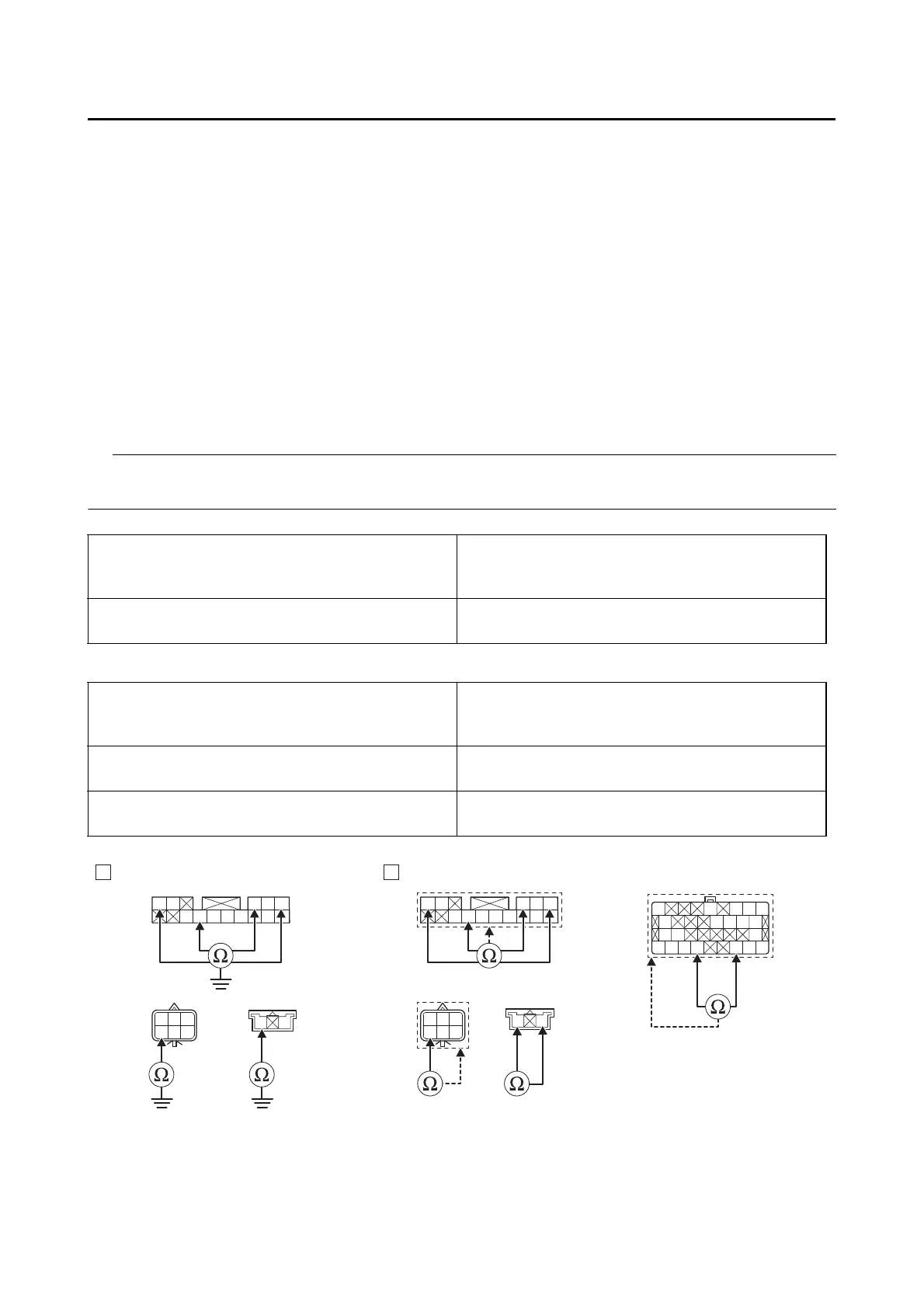
• Short circuit check
Disconnect the ECU related connectors before checking.
Refer to “PARTS CONNECTED TO THE ECU” on page 9-4.
Ground short circuit check “A”
Lines short circuit check “B”
Is resistance 0 Ω?
YES
→ Go to “Short circuit check”.
NO
a. Replace the wire harness.
b. Start the engine and let it idle for approximately 5 seconds.
c. Check the condition of the DTC using the malfunction mode of the YDT.
Is it in the “Recovered” condition?
YES
→ Go to step 8, and complete the service.
NO
→ Go to “Short circuit check”.
Between relay unit coupler “2” and ground
brown–ground
blue/white–ground
red–ground
Between handlebar switch (right) coupler “4”
and ground
red/white–ground
red/white–ground
Relay unit coupler “2”
brown–any other coupler terminal
blue/white–any other coupler terminal
red–any other coupler terminal
Handlebar switch (right) coupler “4”
red/white–any other coupler terminal
red/white–any other coupler terminal
ECU coupler “5”
red/blue–any other coupler terminal
blue/white–any other coupler terminal
W
L/W
R
L/B
LB
Sb/W
Sb
W
Br
L/W
RR
W/B W/G B/W
R/W
BW
W
L/W
R
L/B
LB
Sb/W
Sb
W
Br
L/W
RR
W/B W/G B/W
R/W
BW
O
Gy/RO/GP/BY/R
B
R/BG/BL/BLg/R
B
G/YR/L
B/WB/WR/LL/WY/BY/RR/G
BA
R/W L/W
R/W L/W
22
44
5
4
4