9-244
P1806, P1807
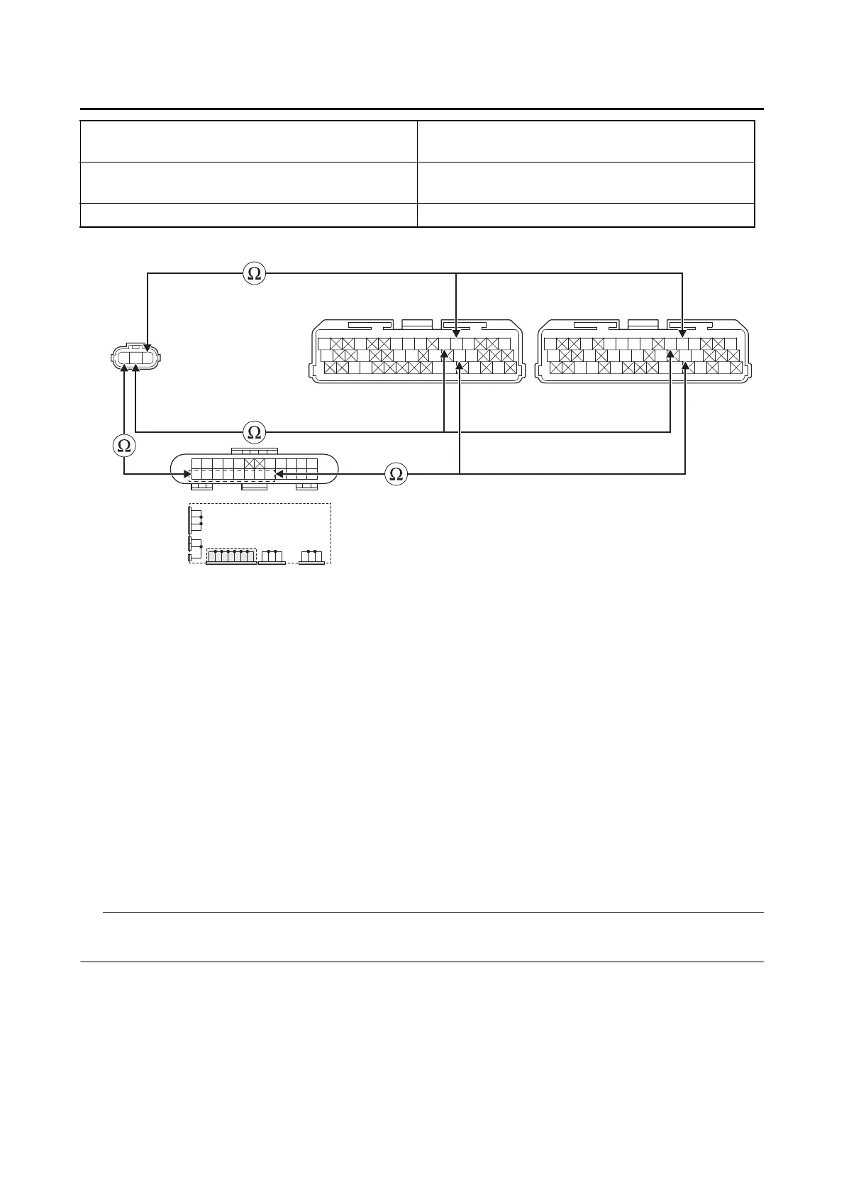
• Short circuit check
Disconnect the ECU related connectors before checking.
Refer to “PARTS CONNECTED TO THE ECU” on page 9-4.
Between shift sensor coupler “1” and ECU cou-
pler “2”
blue–blue
violet–violet
Between shift sensor coupler “1” and joint cou-
pler “3”
black–black
Between joint coupler “3” and ECU coupler “2” black/blue–black/blue
Gy
LLVP
P/WLg/LO/WY/LL/B
B/LB/LBr/WGy/GG/LBr/LB/YL/W
W/YW/GG/WG/WLg/BL/WL/Y
BVL
L/W
WW
L/W
BB
L/B L/B Y/B Y/B
L/R L/R L/RL/RB/L
B
B/L
BBBBB
Gy
LLVP
P/WLg/LY/LL/B
B/LB/LBr/WGy/GG/LB/YL/W
W/YW/GG/WG/WL/WL/Y
2
*
2
**
1
3
*. MTN890
**. MTN890D
Is resistance 0 Ω?
YES
→ Go to “Short circuit check”.
NO
a. Replace the wire harness.
b. Turn the main switch to “ON”, and then check the condition of the DTC using the malfunction
mode of the YDT.
Is it in the “Recovered” condition?
YES
→ Go to step 7, and complete the service.
NO
→ Go to “Short circuit check”.