9-245
P1806, P1807
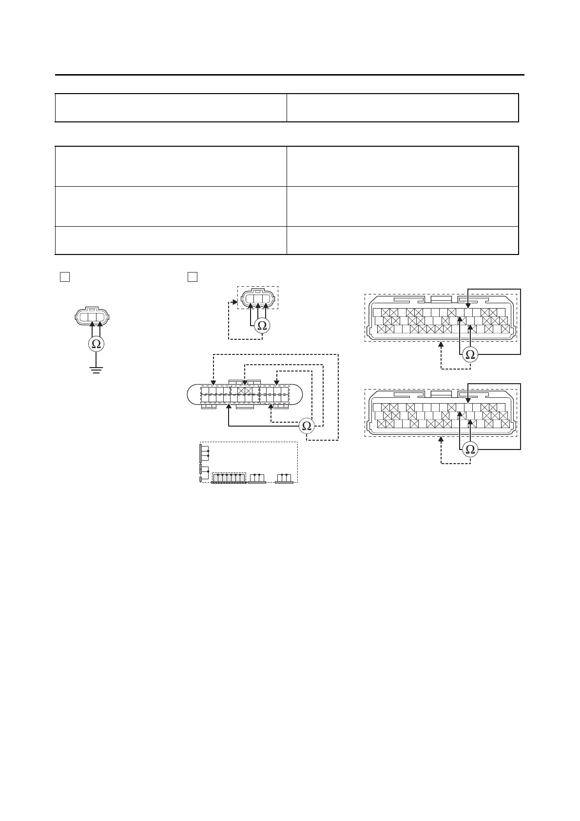
Ground short circuit check “A”
Lines short circuit check “B”
4. Installed condition of shift sensor.
• Check for looseness or pinching.
Between shift sensor coupler “1” and ground
violet–ground
blue–ground
Shift sensor coupler “1”
black–any other coupler terminal
violet–any other coupler terminal
blue–any other coupler terminal
ECU coupler “2”
black/blue–any other coupler terminal
violet–any other coupler terminal
blue–any other coupler terminal
Joint coupler “3”
black/blue–any other coupler terminal
black–any other coupler terminal
Gy
LLVP
P/WLg/LO/WY/LL/B
B/LB/LBr/WGy/GG/LBr/LB/YL/W
W/YW/GG/WG/WLg/BL/WL/Y
BVL
BA
Gy
LLVP
P/WLg/LY/LL/B
B/LB/LBr/WGy/GG/LB/YL/W
W/YW/GG/WG/WL/WL/Y
BVL
2
*
2
**
3
1
1
L/W
WW
L/W
BB
L/B L/B Y/B Y/B
L/R L/R L/RL/RB/L
B
B/L
BBBBB
*. MTN890
**. MTN890D
Is resistance ∞ Ω?
YES
→ Go to step 4.
NO
a. Replace the wire harness.
b. Turn the main switch to “ON”, and then check the condition of the DTC using the malfunction
mode of the YDT.
Is it in the “Recovered” condition?
YES
→ Go to step 7, and complete the service.
NO
→ Go to step 4.
 Loading...


