5.2 I/O Signal (CN1) Connections
5-11
5.2 I/O Signal (CN1) Connections
This section gives the names and functions of the I/O signal pins, as well as connection examples.
Note: This information applies only to the SGDV-MD A01EM3A and SGDV-MD A02E8M3A01.
5.2.1 I/O Signal Names and Functions
The I/O signals are used for the following functions.
•Homing
•Overtravel
• Latching the feedback position with an external signal input
• Controlling the servomotor brake power supply
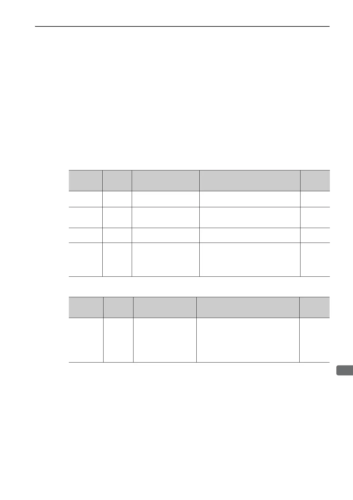
(1) Input Signals
(2) Output Signals
Signal Pin No. Name Function
Refer-
ence
Section
/DEC
Can be allo-
cated.
Homing deceleration
switch signal
Connects the deceleration limit switch for
homing.
5.3.1
P-OT
N-OT
Can be allo-
cated.
Forward run prohibited,
Reverse run prohibited
With overtravel prevention: Stops servomotor
when movable part travels beyond the allow-
able range of motion.
5.3.1
/EXT1 to
/EXT3
Can be allo-
cated.
External latch signals 1 to 3
Connects the external signals that latch the
current feedback pulse counter.
5.3.1
+24VIN 6
Control power supply for
sequence signal
Control power supply input for sequence sig-
nals
Operating range: +21.6 V to +26.4 V
Note: The 24 VDC power supply is not
included.
5.2.4
Signal Pin No. Name Function
Refer-
ence
Section
/BK
1-2, 3-4,
14-15,
17-18,
19-20,
21-22,
23-24,
25-26
Brake output signal
Controls the brake. The brake is released when
the signal turns ON.
7.3.4

 Loading...


