3.1 Servomotors
3-9
3
Specifications and Dimensional Drawings
3.1.3 Mechanical Specifications
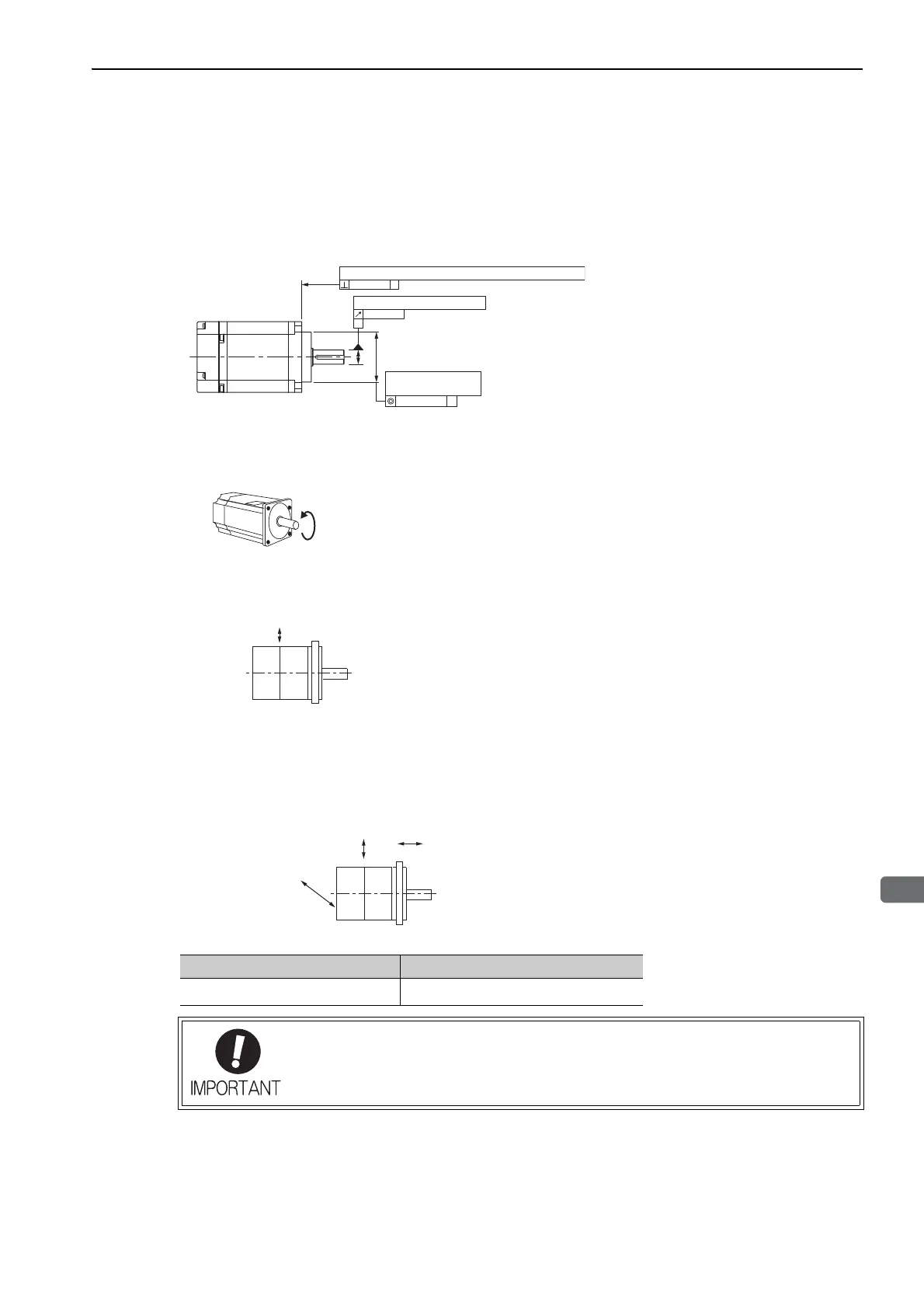
(1) Mechanical Tolerance
The following figure shows tolerances for the servomotor
’
s output shaft and installation area. For more details on
tolerances, refer to the external dimensions of the individual servomotor.
(2) Direction of Servomotor Rotation
(3) Shock Resistance
(4) Vibration Resistance
Mount the servomotor with the axis horizontal. The servomotor will withstand the follow
ing vibration acceleration
in three directions: Vertical, side to side, and front to back.
(5) Vibration Class
The vibration class for the servomotors at rated motor speed is V15. (A vibration class of V15 indicates a total
vibration amplitude of 15 μ m maximum on the servomotor during rated rotation.)
A
A
0.02
0.04
A
0.04 Dia.
Perpendicularity between the flange face and output shaft
Run-out at the end of the shaft
Mating concentricity
of the flange O.D.
Positive rotation of the servomotor without a gear is counterclockwise when
viewed from the load. Refer to Ratings and Specifications for each series regard-
ing rotation direction of the servomotor with a gear. The direction of rotation can
be reversed by changing the SERVOPACK parameters.
Mount the servomotor with the axis horizontal. The servomotor will withstand
the following vertical impacts:
• Impact Acceleration: 490 m/s
2
• Impact occurrences: 2
Vertical
Impact Applied to the Servomotor
Servomotor Model Vibration Acceleration at Flange
SGMMV
49 m/s
2
The amount of vibration the servomotor endures will vary depending on the application.
Check the vibration acceleration being applied to your servomotor for each application.
Horizontal
Impact Applied to the Servomotor
Vertical
Front to Back
Side to
Side

 Loading...


