2 Selecting Products
2.1.1 Servomotors
2-2
2.1 Model Designations
This section describes how to interpret the model numbers of servomotors and SERVOPACKs.
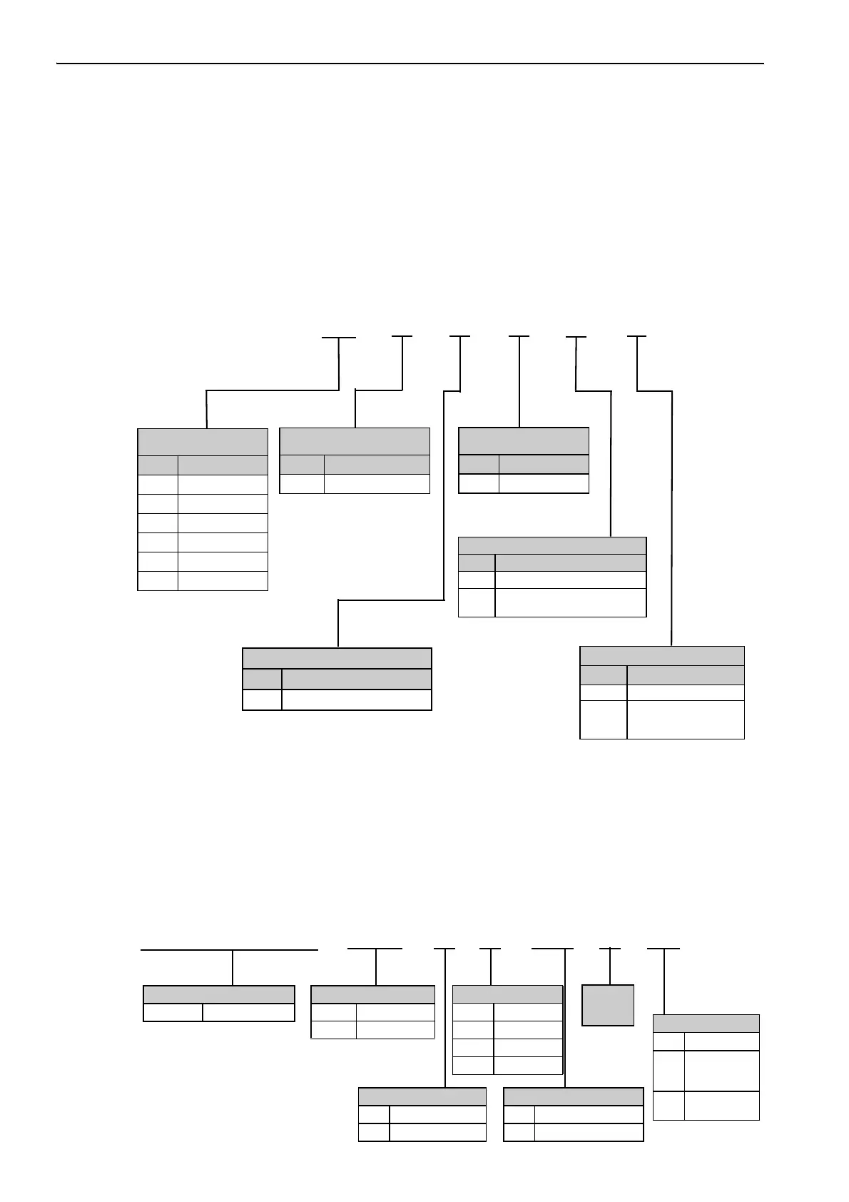
2.1.1 Servomotors
This section describes how to interpret the model numbers of servomotors.
2.1.2 SERVOPACKs
This section describes how to interpret the model numbers of SERVOPACKs.
(1) Type A01 SERVOPACK
A1
A
2
A
1st + 2nd digits:
Rated Output
Code Specification
B3 3.3 W
B5 5.5 W
B9 11 W
A1 10 W
A2 20 W
A3 30 W
∗ The same model is used for
either 24 or 28 VDC. Char-
acteristics depend on the
main circuit voltage of the
SERVOPACK.
3rd digit:
Power Supply Voltage
Code Specification
E
24 or 48 VDC
*
4th digit: Serial Encoder
Code Specification
2
17-bit absolute
1st + 2nd
digits
3rd
digit
4th
digit
5th
digit
–
2
6th
digit
1
7th
digit
7th digit: Options
Code Specification
1 No options
C
With holding brake
(24 VDC, flange size:
25 × 25 mm)
6th digit: Shaft End
Code Specification
2 Straight (standard)
A
Straight with flat seats
(optional)
SGMMV
5th digit: Design
Revision Order
Code Specification
A Standard
MD
A01
Product Type
Code Specification
A01 –
–
SGDV
Series
SGDV-MD Σ-V-MD Series
E8 M3A
02
Number of Axes
Code Specification
4 4 axes
8 8 axes
C 12 axes
Power Supply Voltage
Code Specification
E 24 or 48 VDC
Interface Specification
Code Specification
M3 MECHATROLINK-III
Design
Revision
Order
Options
Code Specification
–
Without
mounting
option
02
With mounting
option
1st
digit
2nd
digit
3rd
digit
4th
digit
5th
digit
6th
digit

 Loading...


