5.2 I/O Signal (CN1) Connections
5-13
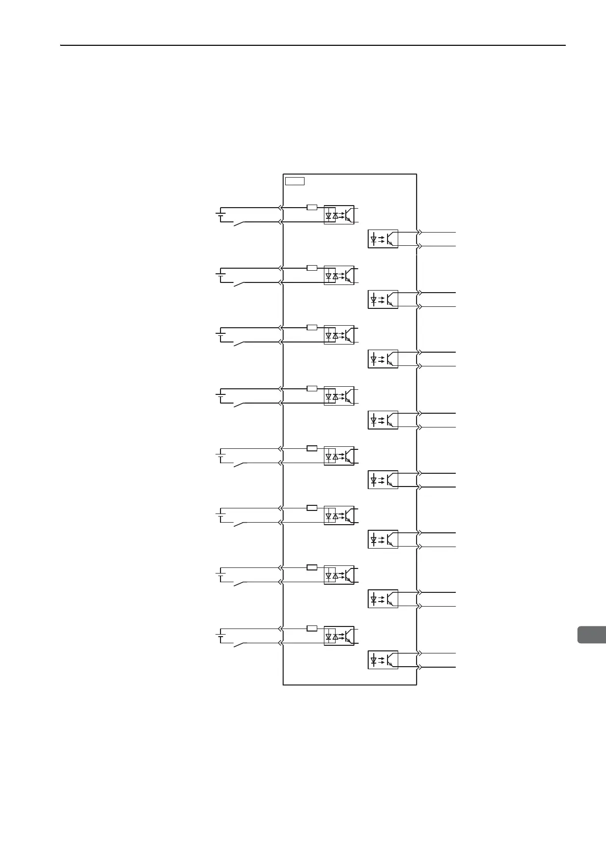
5.2.3 Example of I/O Signal Connections
The following diagram shows a typical connection example.
∗ The 24-VDC power supply is not included. Use a 24-VDC power supply with double insulation or reinforced insula-
tion.
BK-1 (+)
1
+24 VIN
+24 V
∗
4.7 kΩ
6
SI-0
5
BK-1 (-)
Sequence input signal 0
Control power supply
for sequence signal
Brake
(Brake released when ON)
Photocoupler output
Max. operating voltage: 30 VDC
Max. output current: 50 mA DC
SERVOPACK
2
BK-2 (+)
3
+24 VIN
+24 V
∗
4.7 kΩ
6
SI-1
7
BK-2 (-)
Sequence input signal 1
4
BK-3 (+)
14
+24 VIN
+24 V
∗
4.7 kΩ
6
SI-2
8
BK-3 (-)
Sequence input signal 2
15
BK-4 (+)
17
+24 VIN
+24 V
∗
4.7 kΩ
6
SI-3
9
BK-4 (-)
Sequence input signal 3
18
BK-5 (+)
19
+24 VIN
+24 V
∗
4.7 kΩ
6
SI-4
10
BK-5 (-)
Sequence input signal 4
20
BK-6 (+)
21
+24 VIN
+24 V
∗
4.7 kΩ
6
SI-5
11
BK-6 (-)
Sequence input signal 5
22
BK-7 (+)
23
+24 VIN
+24 V
∗
4.7 kΩ
6
SI-6
12
BK-7 (-)
Sequence input signal 6
24
BK-8 (+)
25
+24 VIN
+24 V
∗
4.7 kΩ
6
SI-7
13
BK-8 (-)
Sequence input signal 7
26
CN1

 Loading...


