2.2 Selecting Servomotors
2-5
2.2.2 Selection Calculations
This section describes how to make the calculations and select a servomotor for the following machine speci-
fications.
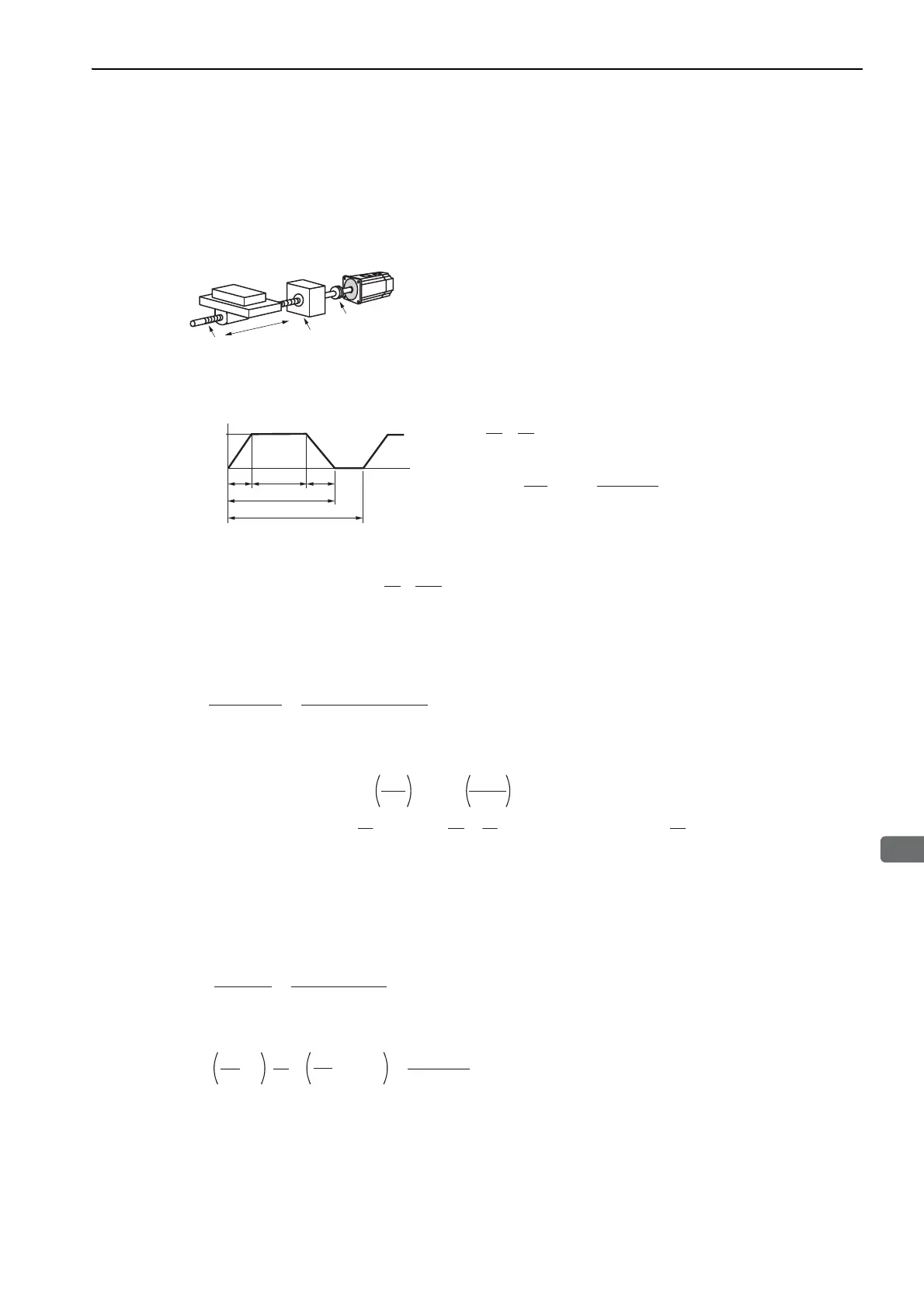
(1) Speed Diagram
(2) Rotation Speed
(3) Load Torque
(4) Load Moment of Inertia
(5) Load Moving Power
(6) Load Acceleration Power
• Load speed:
υ
L
= 15 m/min
• Linear motion section mass:
m
= 250 kg
• Ball screw length: l
B
= 1.0 m
• Ball screw diameter: d
B
= 0.02 m
• Ball screw lead: P
B
= 0.01 m
• Ball screw material density
:
ρ
= 7.87 × 10
3
kg/m
3
• Gear ratio : 1/2 (R = 2)
• Gear + coupling moment of inertia:
J
G
= 0.40 × 10
-4
kgm
2
• Feeding times: n = 40 times/min
• Feeding distance: l = 0.275 m
• Feeding time: tm = 1.2 s max.
• Friction coefficient:
μ
= 0.2
• Mechanical efficiency:
η
= 0.9 (90%)
Servomotor
Coupling
Ball screw
Gear
Linear motion
Mechanical Specifications
L
υ
tcta td
(
m/min
)
Speed
Time (s)
tm
t
L
15
υ
t
===
1
.
5
㧔
s
㧕
where ta = td
ta
=
tm
−=
1
.
2
− =
1
.
2
−
1
.
1
=
0
.
1
㧔
s
㧕
tc
=
1
.
2
−
0
.
1
×
2
=
1
.
0
㧔
s
㧕
60
n
60
40
60
×
0
.
275
15
60
ℓ
L
υ
Load axis rotation speed
nL
== =
1500
㧔
min
-1
㧕
PB
15
0
.
01
L
υ
Motor shaft rotation speed Gear ratio 1/R = 1/2 (R=2)
Therefore,
nM
=
nL
R
=
1500
×
2
=
3000
㧔
min
-1
㧕
TL
=
==
0
.
43
(
N
・
m
)
2
R
・
9
.
8
・
m
・
PB
2
2
0
.
9
9
.
8
0
.
2
250
0
.
01
μ
η
Linear motion section
JL1
=
m
=
250
× =
1
.
58
×
10
-4
㧔
kg
㨯
m
2
㧕
2
2
π
R
P
B
2
2
π
×
2
0
.
01
Ball screw
JB
=
ℓB
dB
4
= ×
7
.
87
×
10
3
×
1
.
0
×
㧔
0
.
02
㧕
4
=
0
.
31
×
10
-4
㧔
kg
㨯
m
2
㧕
R
2
1
32
π
2
2
1
32
π
ρ
Coupling
JG
=
0
.
40
×
10
-4
㧔
kg
m
2
㧕
Load moment of
inertia at motor shaft
JL
=
JL1
+
JB
+
JG
=
㧔
1
.
58
+
0
.
31
+
0
.
40
㧕
×
10
-4
=
2
.
29
×
10
-4
㧔
kg
m
2
㧕
PO
=
= =
135
(
W
)
60
2
nM
・
TL
60
2
3000
0
.
43
Pa
=
= =
226
(
W
)
nM
2
60
2
ta
J
L
3000
2
60
2
0
.
1
2
.
29
10
-4

 Loading...


