5 Wiring and Connections
5-18
5.4 Wiring MECHATROLINK-III Communications
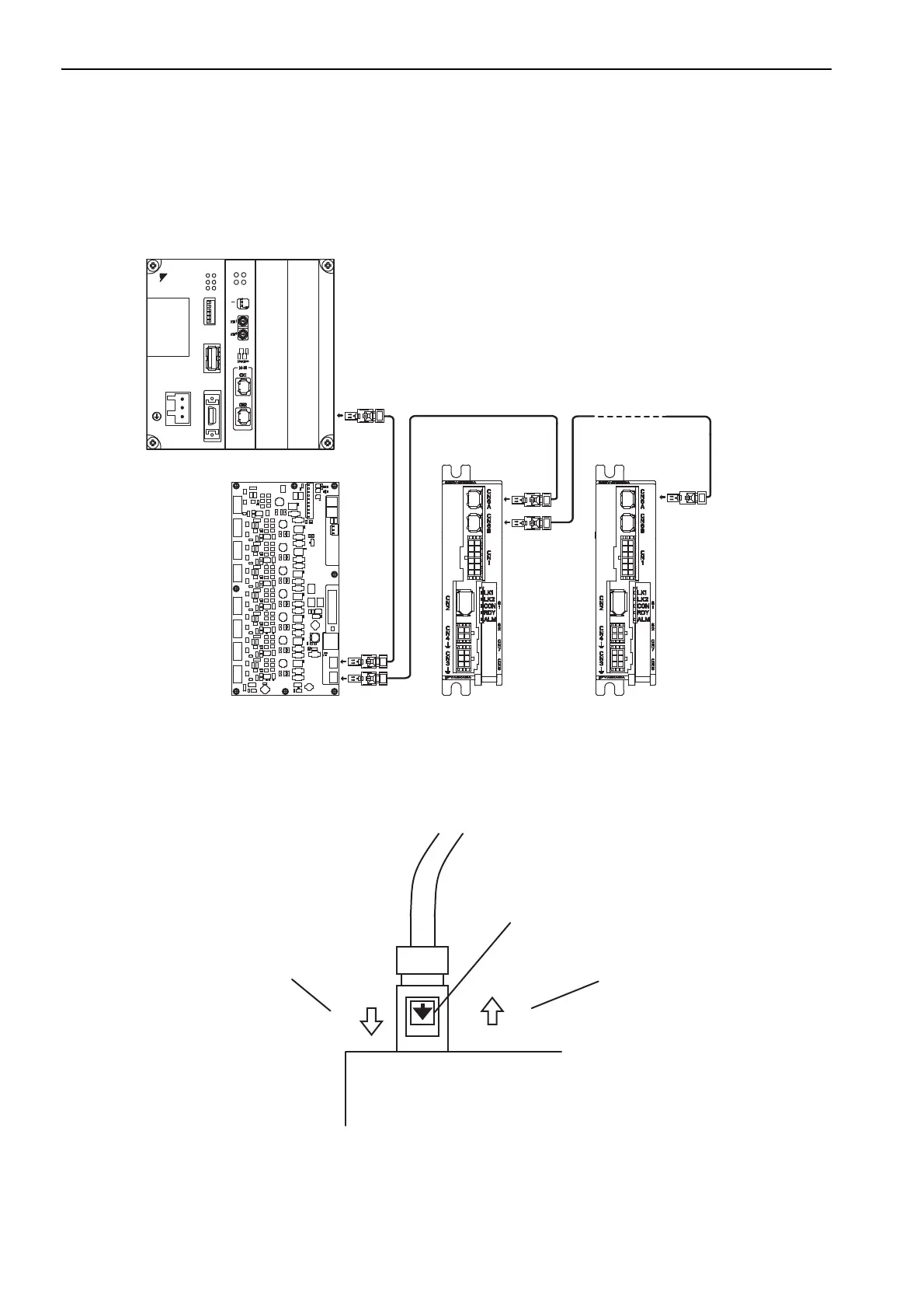
The following diagram shows an example of connections between a host controller and a SERVOPACK using.
MECHATROLINK-III communications cables (CN6A, CN6B).
Note: The length of the cable between stations (L1, L2 ... Ln) must be 50 m maximum.
For removing the MECHATROLINK-III communications cable connectors from the SERVOPACK, refer to
the following procedure.
Slide the lock injector of the connector to the SERVOPACK side to unlock and remove the MECHA-
TROLINK-III communications cable connectors.
Note: The MECHATROLINK-III communications cable connector may be damaged if it is removed without being
unlocking.
Ln
L1
L2
DC24V
DC 0V
MP2300
YAS KAWA
TEST
Option
Option
RDY
ALM
TX
RUN
ERR
BAT
MON
CNFG
INT
SUP
STOP
SW1
OFF ON
BATTERY
CPU I/O
M-I/II
SVC-01
ERR
LK2
RUN
LK1
M/S
ONOFF
SERVOPACK
Lock injector
1. Slide the lock injector to
the SERVOPACK side.
2. Remove the connector
while the lock injector is
slid to the SERVOPACK
side.

 Loading...


