5.2 I/O Signal (CN1) Connections
5-15
5.2.5 Sequence Output Circuit
The signal output circuit from the SERVOPACK is described below.
(1) Photocoupler Output Circuit
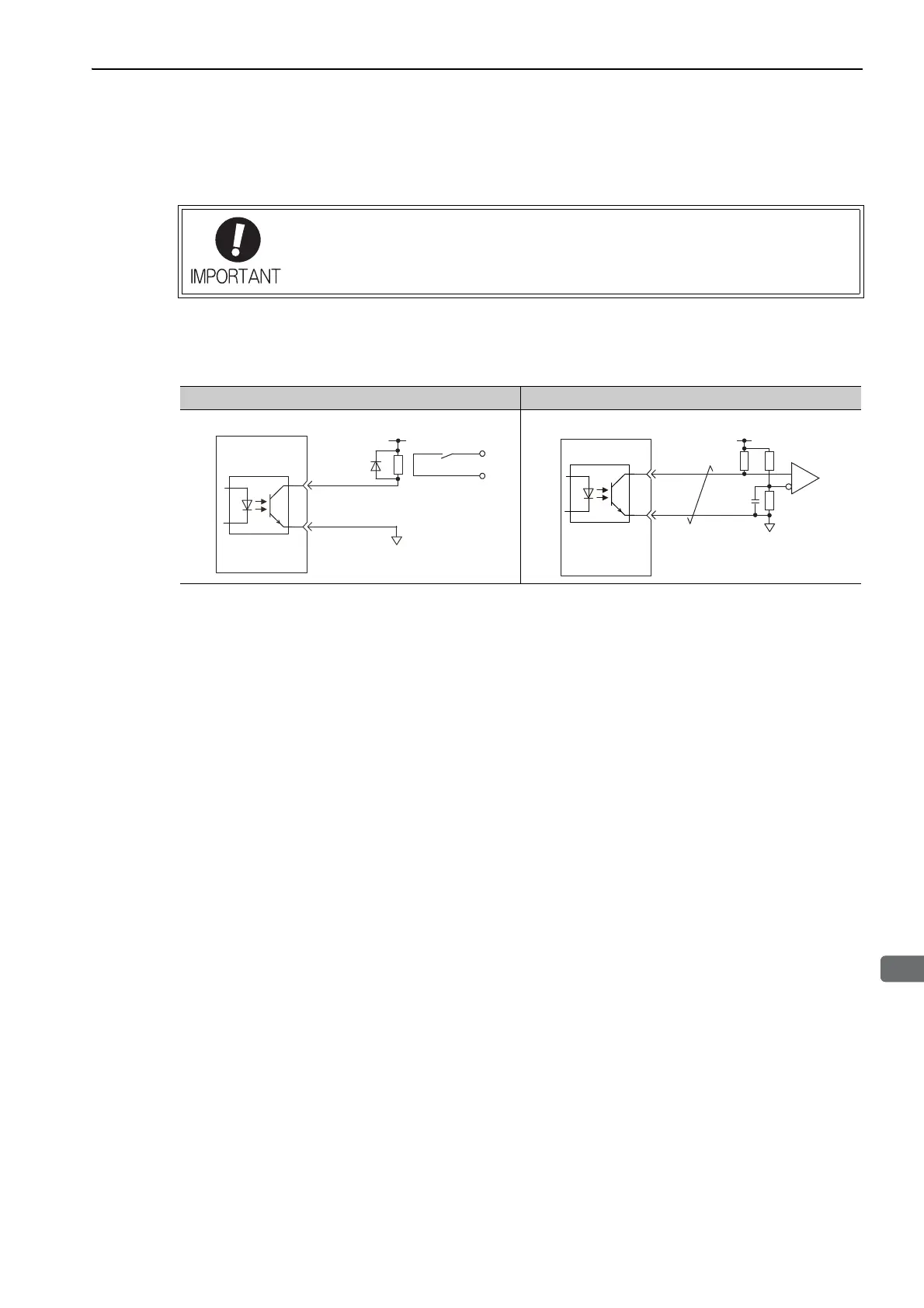
The brake signal (/BK) output signal uses a photocoupler output circuit. Connect a photocoupler output circuit
through a relay circuit or line-receiver circuit.
Note: The maximum allowable voltage and the allowable range of current capacity for photocoupler output circuits are as
follows.
•
Voltage: 30 VDC
•
Current: 5 to 50 mA DC
Incorrect wiring or incorrect voltage application to the output circuit may cause short-cir-
cuit.
If a short-circuit occurs as a result of any of these causes, the holding brake will not
work. This could damage the machine or cause an accident resulting in death or injury.
Relay Circuit Example Line Receiver Circuit Example
0V
Relay
5 to 24 VDC
SERVOPACK

 Loading...


