2.3 Connecting Devices
2.3.1 Part Names and Functions
2-37
2
Installation and Connections
2.3
Connecting Devices
This section explains how to connect devices to the MP3000-series Controllers.
2.3.1
Part Names and Functions
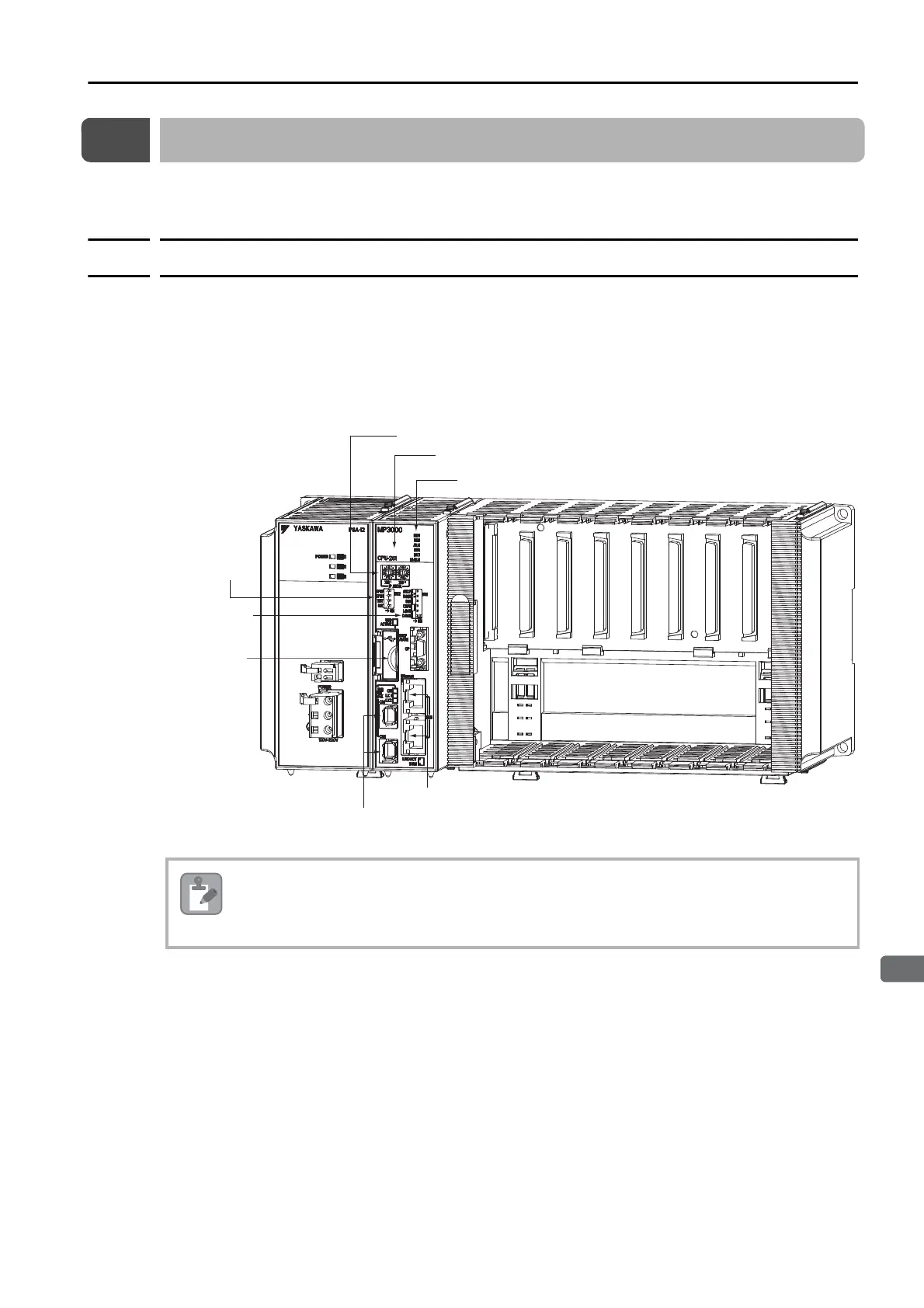
The following figure shows the names and functions of the parts of the Machine Controller and
the Servo Drive.
Machine Controller
MP3200
If the CN1 and CN2 MECHATROLINK-III connectors and the Ethernet connectors are all used,
connecting and disconnecting the Ethernet connector at the bottom may be difficult. Therefore,
we recommend that you use the bottom Ethernet connector for devices that can normally be left
connected.
USB
connector
Ethernet connectors
MECHATROLINK-III connectors (2 ports)
DIP switch
(6 pins)
DIP switch
(4 pins)
Indicators (6)
Seven-segment display
Rotary switches (2)

 Loading...


