2.3 Connecting Devices
2.3.2 Connecting the Power Supply Connector
2-43
2
Installation and Connections
Cable for a 24-VDC Power Supply
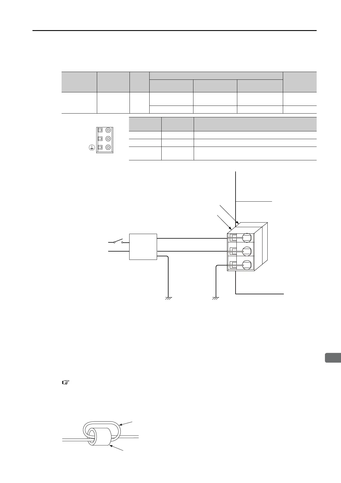
The power supply for the Machine Controller is 24 VDC. Refer to the following figure for the
connection methods.
Note: Use an isolating 24-VDC power supply, and install the power supply switch on the AC side of the
power supply. If the switch is installed on the 24-VDC side, the inrush current may reach approx. 40
A when the power is turned ON.
Procedure to Make a 24-VDC Power Cable
The power supply pins are contained in a removable connector. Use the following procedure to
wire the power supply connector. Use a twisted-pair cable with a wire size of AWG28 to
AWG13 (0.08 to 2.6 mm
2
) to connect the 24-VDC power supply to the power supply connector
on the Controller.
The procedure to make the cable is the same as for the 100/200-VAC power supply cable.
Procedure to Make a 100/200-VAC Power Cable (page 2-42)
When Using the CPU-202 (Model: JEPMC-CP3202-E)
Wrap the power cable twice near the connector and install the ferrite core packaged with the
CPU-202.
Name
Connector
Label
Num-
ber of
pins
Connector Models
Remarks
Module Side Cable Side Manufacturer
Power
Connector
POWER 3
721-863 721-203/026
WAGO Company
of JAPAN
MP3200
4-2013519-3 4-2013522-3 TE Connectivity MP3300
Pin No.
Signal
Label
Description
3 24 VDC Power input wire for 24 VDC
2 0 VDC Power input wire for 0 VDC
1FG
Connects to the frame ground. (Ground to 100 Ω
max.)
24 VDC
0 VDC
POWER
0 V
POWER
FG
721-863 or
4-2013519-3
721-203/026 or
4-2013522-3
FG
24-VDC
power
supply
AC input
24 VDC
Machine Controller

 Loading...


