2.3 Connecting Devices
2.3.4 Connecting the Power Supply and Other Devices
2-46
4.
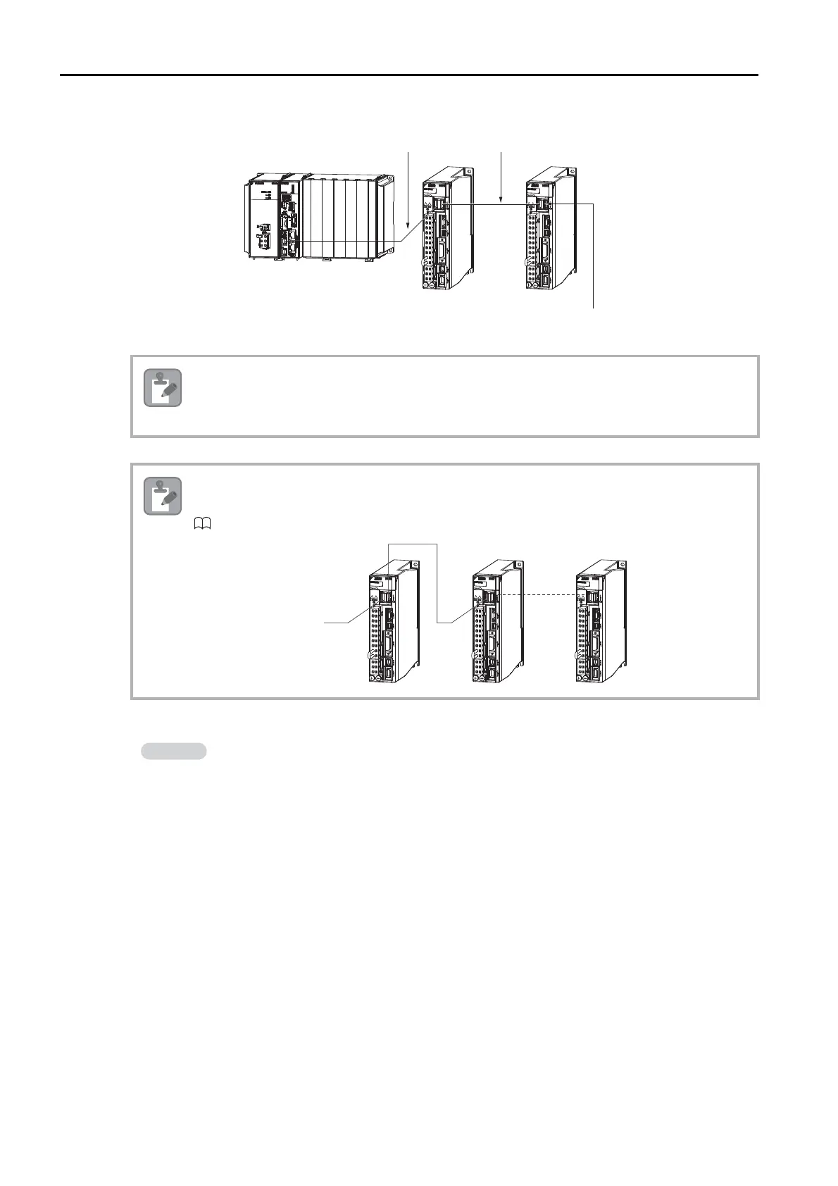
Connect the devices using the MECHATROLINK-II or MECHATROLINK-III cables.
5.
Set the station addresses of the SERVOPACKs.
• If more than one SERVOPACK is connected with MECHATROLINK-II Communications Cables,
install a Terminator on the last SERVOPACK.
• If more than one SERVOPACK is connected with MECHATROLINK-III Communications Cables,
a Terminator is not required on the last SERVOPACK.
If there is more than one Servo Drive, connect them in the same way. You can use either cascade
connections or star configurations. The following figure shows an example of cascade
connections. Refer to the following manual for details.
MECHATROLINK-III I/O Module User’s Manual (Manual No.: SIEP C880781 04)
The following is an example of the station address settings.
MECHATROLINK-II: The figures show the settings when the address of axis 1 is 1, and the
address of axis 2 is 2.
MECHATROLINK-III: The figures show the settings when the address of axis 1 is 3, and the
address of axis 2 is 4.
Note: For MECHATROLINK-III, start setting the station addresses from 3.
MECHATROLINK-II cables
To prevent communications errors, conrm that
the connectors are properly inserted.
Note
Note

 Loading...


