6.1 I/O Signal Allocations
6.1.1 Input Signal Allocations
6-5
Changing Input Signal Allocations
The input signals that you can allocate to the pins on the I/O signal connector (CN1) and the
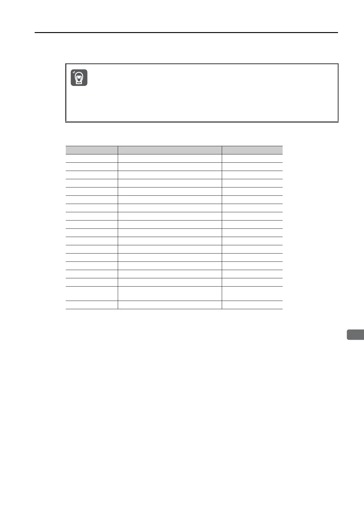
related parameters are given in the following table.
• If you change the default polarity settings for the /S-ON (Servo ON), P-OT (Forward Drive Pro-
hibit), or N-OT (Reverse Drive Prohibit) signal, the main circuit power supply will not be turned
OFF and the overtravel function will not operate if there are signal line disconnections or other
problems. If you must change the polarity of one of these signals, verify operation and make
sure that no safety problems will exist.
• If you allocate two or more signals to the same input circuit, a logical OR of the inputs will be
used and all of the allocated signals will operate accordingly. This may result in unexpected
operation.
Input Signal Input Signal Name Parameter
/S-ON Servo ON Pn50A = n.X
/P-CON Proportional Control Pn50A = n.X
P-OT Forward Drive Prohibit Pn50A = n.X
N-OT Reverse Drive Prohibit Pn50B = n.X
/ARM-RST Alarm Reset Pn50B = n.X
/P-CL Forward External Torque Limit Pn50B = n.X
/N-CL Reverse External Torque Limit Pn50B = n.X
/SPD-D Motor Direction Pn50C = n.X
/SPD-A Internal Set Speed Selection Pn50C = n.X
/SPD-B Internal Set Speed Selection Pn50C = n.X
/C-SEL Control Selection Pn50C = n.X
/ZCLAMP Zero Camping Pn50D = n.X
/INHIBIT Reference Pulse Inhibit Pn50D = n.X
/G-SEL Gain Selection Pn50D = n.X
/P-DET Polarity Detection Pn50D = n.X
SEN Absolute Data Request Pn515 = n.X
/PSEL
Reference Pulse Input Multiplication
Switch
Pn515 = n.
X
FSTP Forced Stop Pn516 = n.X