7-21
IM AQ6370D-01EN
Analysis
7
Analysis of optical amp gain and NF is performed after measuring the signal light going
into the optical amp and the output light leaving the optical amp.
Acquiring Waveforms Required for Analysis
The following configuration and general procedure is used to measure optical amp gain
and NF.
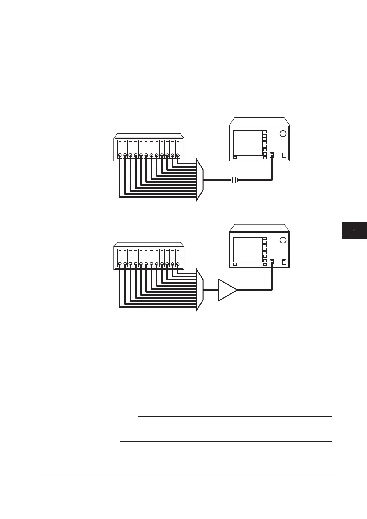
Signal light measurement configuration
Multi-channel light source
MUX
Output light measurement configuration
Multi-channel light source
MUX
Optical amplifier
Writing the Waveform of the Signal Light Input to the Optical Amp on Trace A
1.
Input the signal light sent to the optical amp into the instrument.
2.
Press TRACE followed by the ACTIVE TRACE soft key, then select A.
3.
Press the VIEW A soft key and select DISP.
4.
Press the WRITE A soft key. Trace A enters write mode.
5.
Measure the signal light waveform according to measurement conditions matching
the signal light waveform.
(For details on the measuring procedure, see chapter 5, “Measurement.”)
6.
Press the FIX A soft key under TRACE. Trace A enters fixed mode.
Note
If all traces from trace A to trace G have been set to fix mode (FIX) as a result of this action, a
warning is displayed. However, this does not pose a problem because trace B is set to write
mode in the next step.
7.8 Optical Amp Gain and NF Measurement

 Loading...


