Installation and Communication
37
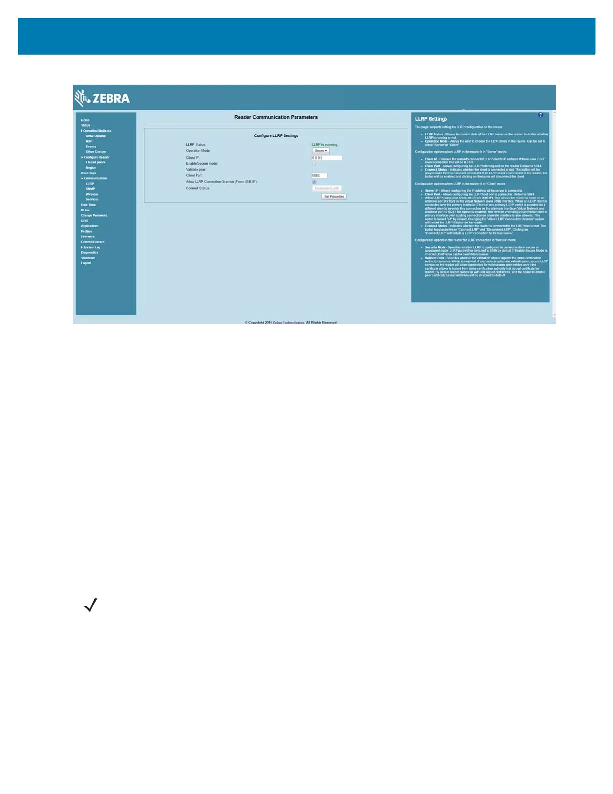
Figure 21 Communication / Configure LLRP Settings Window
Only one LLRP session can be active on the reader, either through the primary Ethernet interface or
through the virtual network over USB interface.
If a connection is active on one interface, a subsequent connection attempt on a second interface
disconnects the first. The second connection attempt always prevails and creates a new session.
GPIO Interface Connection
This pluggable terminal block allows connecting individual wires independently. A single connector
accommodates both inputs and outputs and a +24 VDC supply pin for external sensors and signaling
devices. See Table 11 on page 134 for pinout information. The GPIO interface is electrically isolated from
the reader's chassis ground, but its ground is common to the power return of the 24 VDC external supply
when this is present.
GPIO signals allow some flexibility. Inputs are pulled up within the reader to +5 VDC and can be shorted to
ground to pull them low. They are broadly compatible with industrial sensors with NPN outputs and may
also be connected directly to relays or switch contacts. Alternatively, they can be driven by 5V logic. In the
logic low state, the current sourced from the reader is approximately 3 mA, so standard gates in most logic
families can drive them directly. Current flow in the logic high state is close to zero. Although the GPIO
interface is fully operational in all power modes, the +24 VDC supply is only available when an external
supply is present.
The general-purpose outputs are open-drain (NPN type) drivers, pulled up to 5V. Each output can
withstand voltages up to +30 VDC but should not be driven negative. Drive 24V relays, indicator lamps,
etc., by wiring them between the +24 VDC supply pin and the general purpose output pins. Although each
output can sink up to 1A, the maximum current that can be drawn from the internal 24V supply is 1A, so
use an external power supply if the current requirements exceeds this. Note that the state of the general
purpose outputs is inverted, i.e., driving a control pin high at the processor pulls the corresponding output
low.
NOTE: Do not connect the +24 VDC output directly to any of the general purpose inputs. Although
these can withstand voltages above 5V, they are designed to operate optimally in the range of 0 to +5
VDC.
 Loading...


