2
Description of Individual Parts
- 2.2
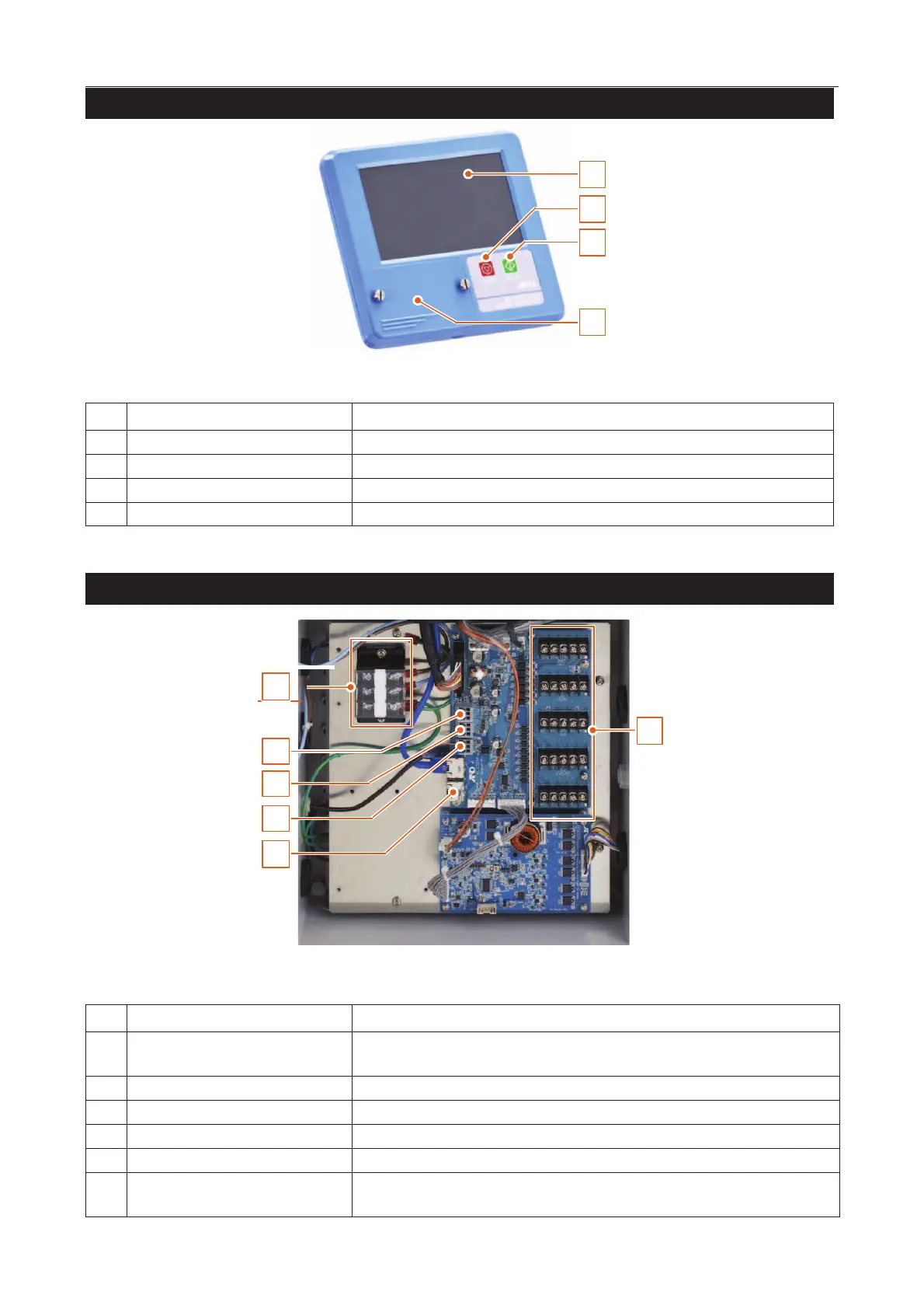
Display Module
8
2
2
1
4
3
Displays data and allows operation of the AD-4971.
Stops the conveyor belt and finishes the inspection.
Starts the conveyor belt and begins the inspection.
A waterproof cover for a USB terminal is attached.
I/O Box (Input & Output Module)
1
2
3
4
5
6
Connects the power wires to terminals (Upper : Live, Middle : Neutral, Lower :
Power ground (earth)).
Connects the serial communication wires.
Connects the Modbus communication wires.
Connects the PE sensor wires.
General purpose input & output
terminal
Connects to receive data from peripherals and to output data of the results.