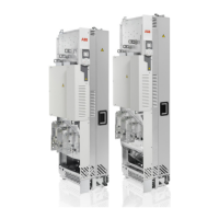
■ Power cable connection process
See chapter Installation example of drive module with IP20 shrouds (option
+B051) (page 113) for instructions on how to connect the input and motor cables.
DC connection
The UDC+ and UDC- terminals are intended for common DC configurations of a number
of drives. A common DC configuration lets regenerative energy from one drive be
utilized by the other drives in the motoring mode. For more information, contact your
local ABB representative.
Connecting the control cables
■ Integrated control unit
This procedure applies to the standard drive module with integrated control unit.
2 × Combi screw
M4×8 Torx T20
2 N·m
1
5
3
(1.5 lbf·ft)
1. Remove the middle front cover of the drive module.
2. Attach the option modules if not attached already. See section Installing option
modules (page 110).
3. Lead the control cables inside the drive cabinet.
4. Ground the outer control cable shields 360° at the cabinet cable entry plate
(recommendation).
Electrical installation 107

 Loading...