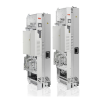
■ Removing the protective covering from the drive module air outlet
WARNING!
Remove the protective covering from the top of the drive module after the
installation. If the covering is not removed, the cooling air cannot flow freely
through the module and the drive will overheat.
Miscellaneous
■ Installations with input and motor cables of size 4 × 240 mm
2
per
phase
If resistor cables are to be connected, the lower side plate of the output cabling panel
must be removed and the resistor cables lead from side to the terminals of the output
cabling panel.
■ Installing the rubber grommet
To get IP20 degree of protection for the drive module, install the input power cables
through the rubber grommet. Install the grommet as follows:
1. Cut adequate holes into the grommet for the input power cables.
2. Put the cables through the grommet.
3. Attach the grommet to the input cabling panel with five M4×8 Torx T20 screws
as shown below.
132 Installation example with full cabling panels (option +H381)

 Loading...