A
B
C
7
4
4
3
1
5
5
2
8
17
18
11
10
12
15
16
20
9
13
6
19
14
Auxiliary voltage transformer T2110Cabinet door closedA
Motor cable connection terminals11Cabinet door openB
Note:
For drives with no du/dt filter (option +E205), the
motor cables are connected to the drive module
terminals.
Input cable connection terminals12Cabinet door open, mounting plate and cabinet
shrouds removed
C
Main switch with AC fuses (Q1)13Drive control panel1
Main contactor (Q2, option +F250)14Operating switch2
Power cable connection terminals of the drive
module behind the shroud
15Main switch handle3
Drive module16Gratings for cooling air in4
Additional I/O terminal block (option +L504)17Gratings for cooling air out5
Drive control unit18
Mounting plate, see section Mounting plate – R6
to R9 (page 36)
6
Common mode filter (option +E208)19Lifting lugs7
du/dt filter (option +E205)20Cabinet door fan8
-Power and control cable entries9
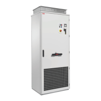
■ Cabinet layout – R8 and R9 (bottom entry and exit of cables)
The cabinet layout of frame R9 with du/dt filter (option +E205) is shown below. Degree of
protection IP42 (option +B054). Frame R8 looks similar.
34 Operation principle and hardware description

 Loading...