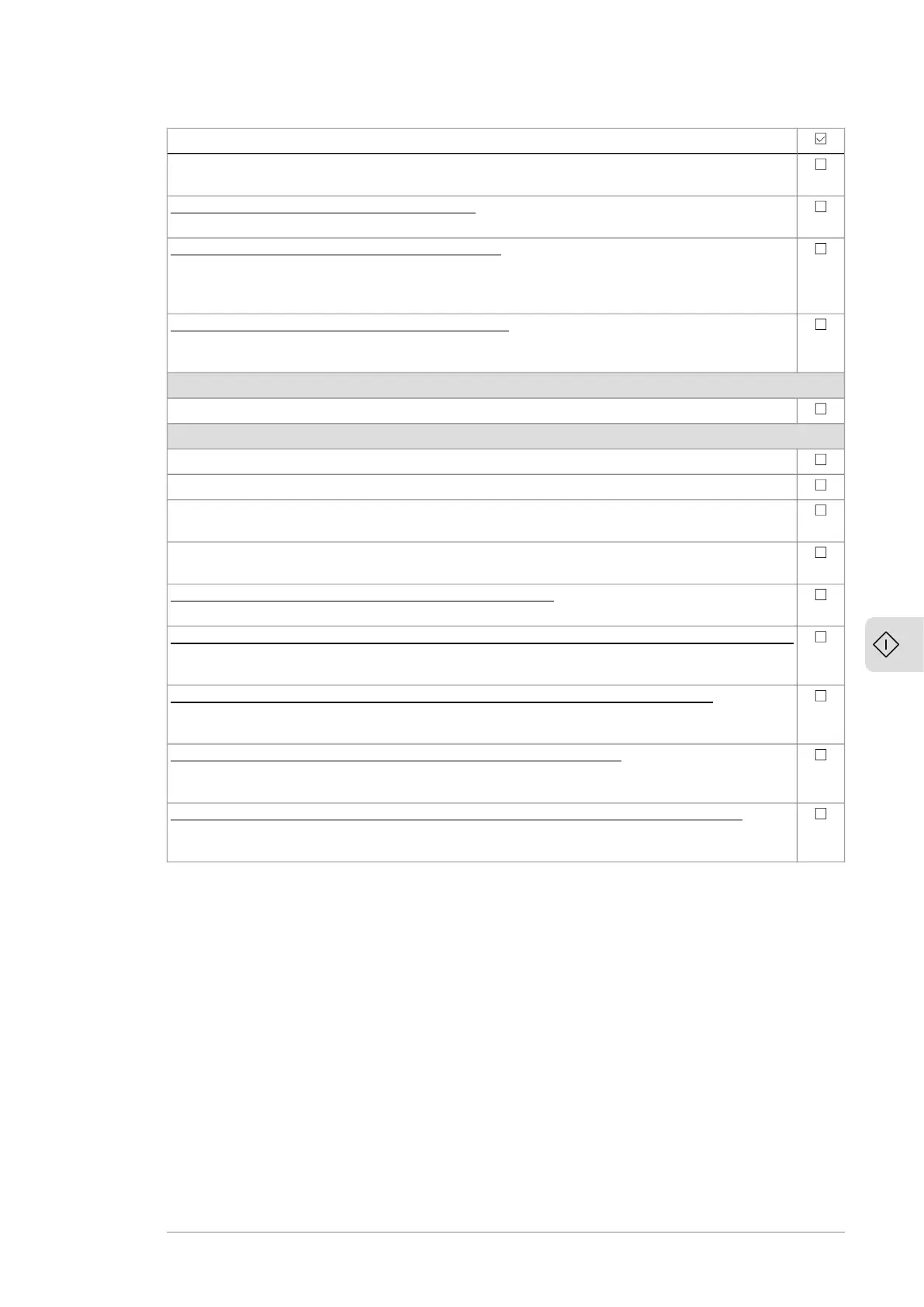
Action
With inverter units consisting of frame R8i modules, check the setting of parameter 95.09 Switch
fuse controller.
Drives with a sine output filter (option +E206): Make sure that bit 1 of parameter 95.15 Special
HW settings is activated.
Drives with an fieldbus adapter module (optional): Set the fieldbus parameters. Activate the
appropriate assistant (if present) in the control program, or see the user’s manual of the fieldbus
adapter module, and the drive firmware manual. Check that the communication works between
the drive and the PLC.
Drives with an encoder interface module (optional): Set the encoder parameters. Activate the
appropriate assistant (if present) in the control program, or see the user’s manual of the encoder
interface module, and the drive firmware manual.
Powering up the main circuit of the drive
Start the supply unit according to the instructions in its hardware manual.
On-load checks
Start the motor to perform the ID run.
Make sure that the cooling fans rotate freely in the right direction, and the air flows upwards.
Make sure that the motor starts, stops and follows the speed reference in the correct direction
when controlled with the control panel.
Make sure that the motor starts, stops and follows the speed reference in the correct direction
when controlled through the customer-specific I/O or fieldbus.
Drives in which the Safe torque off control circuit is in use: Test and validate the operation of
the Safe torque off function. See section Validation test procedure (page 200).
Drives with an emergency stop function (option +Q951, +Q952, +Q963, +Q964, +Q978, or +Q979):
Test and validate the operation of the emergency stop function. Refer to the delivery-specific
circuit diagrams and the applicable safety option user's manual.
Drives with a Prevention of unexpected start-up function (option +Q950 or +Q957): Test and
validate the operation of the POUS function. Refer to the delivery-specific circuit diagrams and
the applicable safety option user's manual.
Drives with a Safely-limited speed function (option +Q965 or +Q966): Test and validate the op-
eration of the SLS function. Refer to the delivery-specific circuit diagrams and the applicable
safety option user's manual.
Drives with a motor thermal protection function (option +L513, +L514, +L536, or +L537): Test
and validate the operation of the motor thermal protection function. Refer to the delivery-spe-
cific circuit diagrams and the applicable safety option user's manual.
Start-up 101

 Loading...


