Connecting the motor cable – Frame sizes R1i…R5i
■
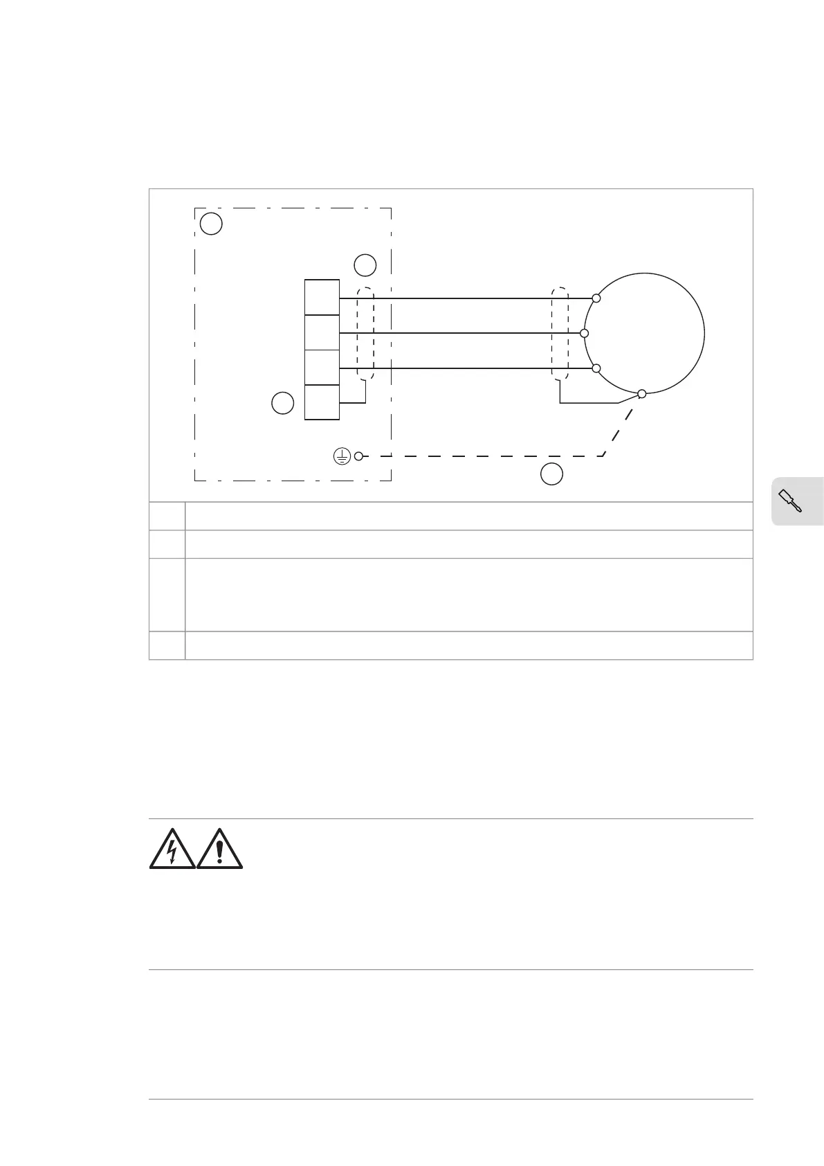
Connection diagram
Inverter unitA
360° grounding at cable entry1
Use a separate grounding cable if the conductivity of the cable shield is less than 50% of the
conductivity of the phase conductor in a cable with no symmetrically constructed grounding
conductor. See ACS880 multidrive cabinets and modules electrical planning instructions
(3AUA0000102324 [English]).
2
If the inverter unit does not have terminal X1:4, connect the cable shield directly to the PE busbar.3
If there is a symmetrically constructed grounding conductor in the motor cable in
addition to the conductive shield, connect the grounding conductor to the grounding
terminal at the drive and motor ends.
Do not use an asymmetrically constructed motor cable. Connecting its fourth conductor
at the motor end increases bearing currents and causes extra wear.
■
Motor cable connection procedure
WARNING!
Obey the safety instructions given in ACS880 multidrives cabinets and
modules safety instructions (3AUA0000102301 [English]). If you ignore
the safety instructions, injury or death, or damage to the equipment
can occur.
If you are not a qualified electrical professional, do not do installation
or maintenance work.
1. Do the steps in section Electrical safety precautions (page 44) before you start
the work.
2. Run the cable into the cubicle through one of the cable glands provided. Remove
the outer jacket of the cable wherever it passes through the cable gland.
Electrical installation 47

 Loading...


