■
Inverter module frame sizes R6i and R7i
The inverter cubicle is equipped with cable entries for the motor cables in the floor of
the cubicle. As standard, the output busbars are extended to the lower part of the
cubicle for easy access.
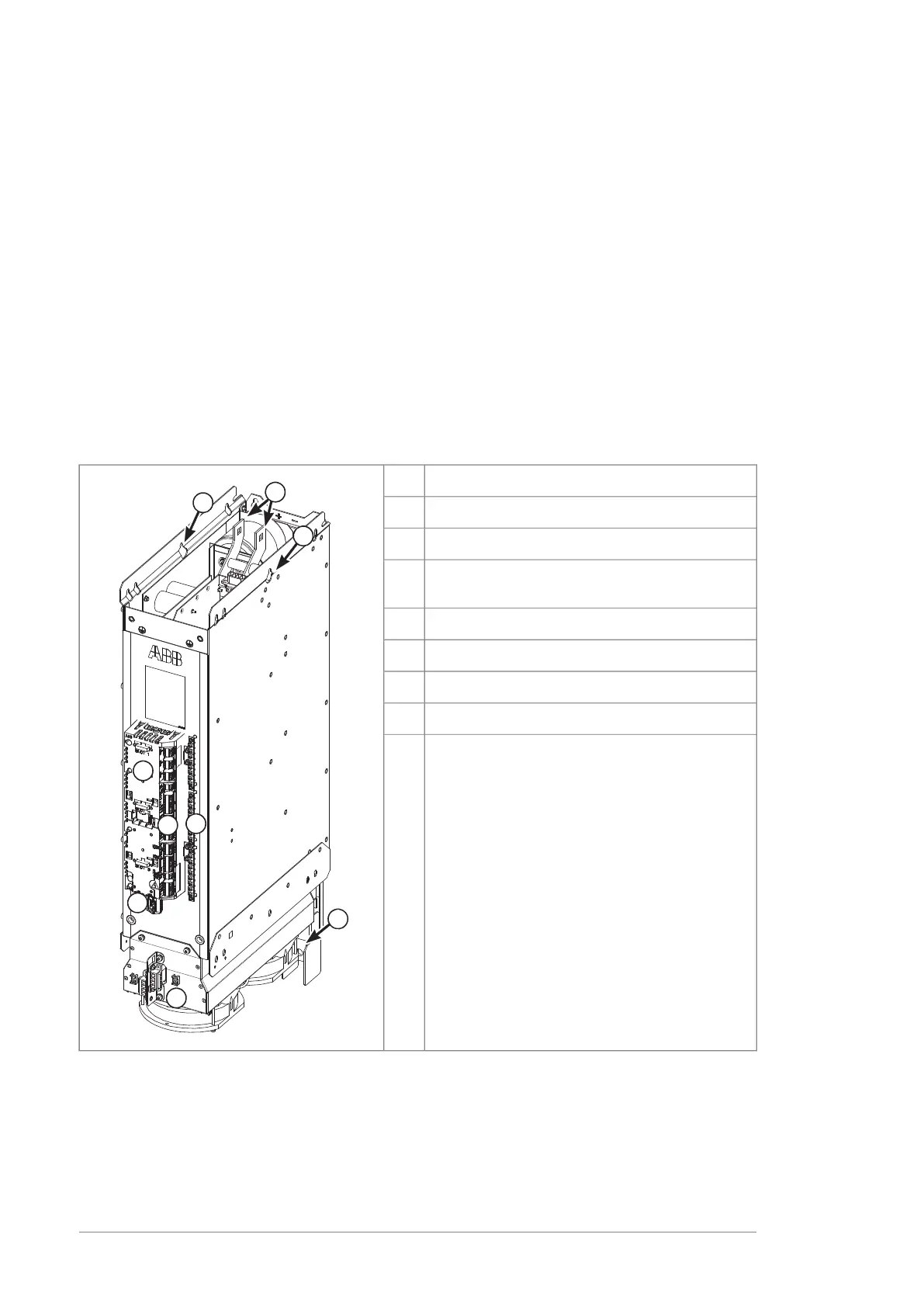
The drive control unit (type ZCU-14) is mounted onto the module. The control unit has
inputs, outputs, and slots for option modules. Other optional equipment is primarily
installed on separate mounting plates.
The cooling fan(s) is supplied from the module and can be easily replaced.
Frame R6i or R7i module with option +V992 is a hardware version that is added to
offering during 2023. Hardware version +V992 is mechanically and electrically
backward-compatible with modules without option +V992. However, ACS880 primary
control program v3.40 and later versions only support option +V992.
Module layout
ExplanationItem
DC (input) connection1
Motor (output) connection2
ZCU-14 control unit (with slots for optional I/O
modules)
3
I/O terminal blocks4
Control panel connector, memory unit5
Grounding/clamping plates for control cables6
Cooling fan holder with one (R6i) or two (R7i) fans7
Lifting eyes8
Cabinet layout
Each inverter module of frame sizes R6i or R7i is installed in a 400 mm wide cubicle.
The modules have a dedicated DC fuses or switch fuse. The modules have an internal
capacitor pre-charge circuit apart from largest R7i types which have an external
charging contactor and resistors.
26 Operation principle and hardware description

 Loading...


