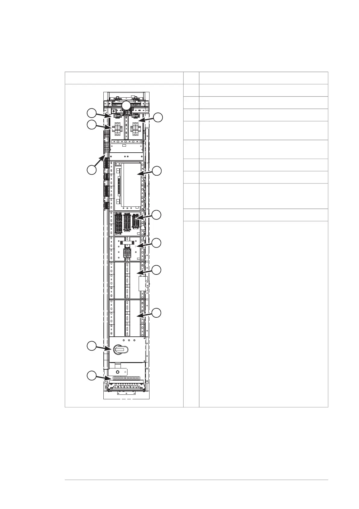
The illustration that follows shows an example of a 300 mm wide control equipment
cubicle.
ExplanationItemFront view
Terminal block for auxiliary voltage distribution1
24 V DC power supply for control circuits2
Circuit breakers for control voltages3
Space for installation of items 2 and 3 for a second
inverter unit
4
(On the left-hand side wall) Terminal blocks for
control circuits and auxiliary voltage distribution
5
Control unit6
Terminal blocks for control unit I/O (option +L504)7
Mounting space for additional or optional circuitry8
…
10
Grounding switch of inverter unit output (optional)11
Control cable entry (optionally on the roof of the
cubicle)
12
Motor cabling
The motor cabling connects to the module via a quick connector at the back of the
module. By default, each inverter module is cabled individually to the motor. With an
optional common motor terminal cubicle, the outputs of the parallel-connected inverter
modules are connected to a separate cubicle containing a single set of output busbars.
Operation principle and hardware description 31

 Loading...


