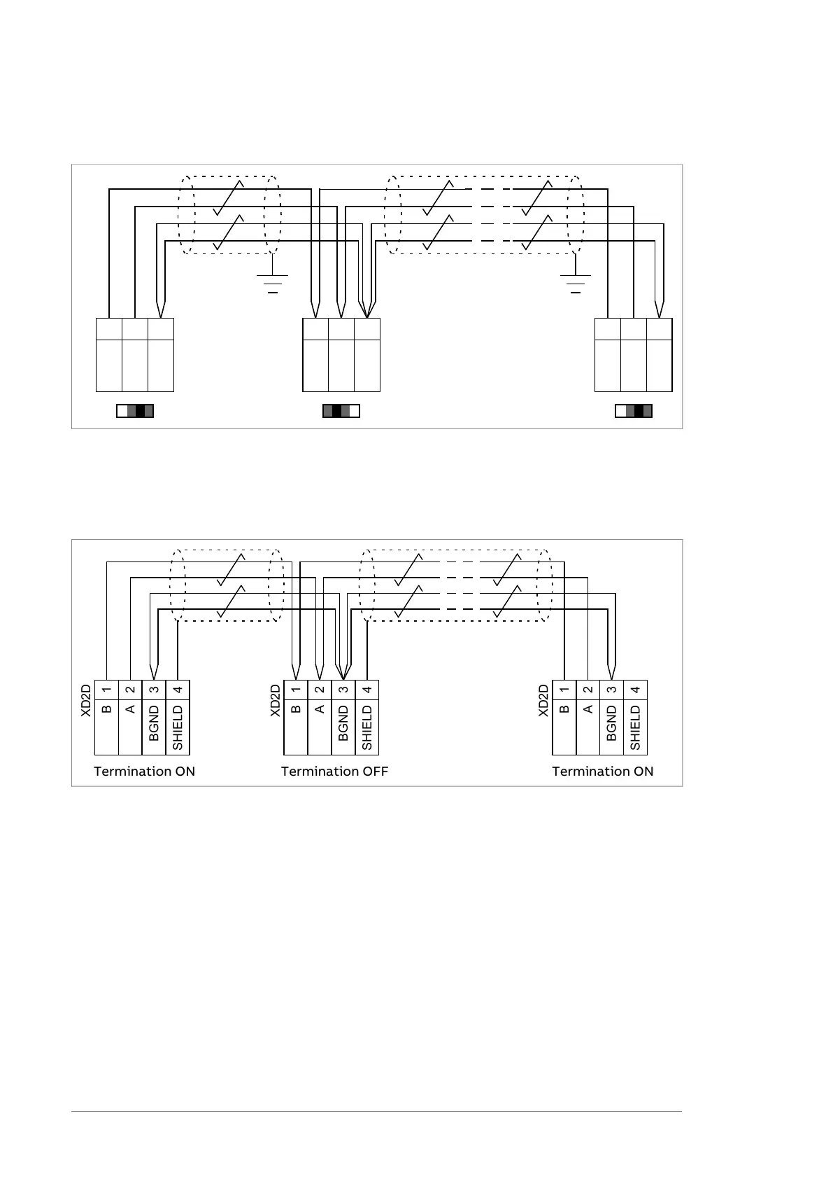
The diagram that follows shows the wiring of the drive-to-drive link. The diagram is
applicable to ZCU-12 control units.
XD2D
XD2D
XD2D
J3J3 J3
1
2
3
B
A
BGND
1
2
3
B
A
BGND
1
2
3
B
A
BGND
The diagram that follows shows the wiring of the drive-to-drive link. The diagram is
applicable to these control units:
• BCU-02/12/22
• ZCU-14
XD2D
XD2D
XD2D
1
2
3
4
B
A
BGND
SHIELD
1
2
3
4
B
A
BGND
SHIELD
1
2
3
4
B
A
BGND
SHIELD
Termination ON Termination ONTermination OFF
■
Safe torque off (XSTO, XSTO OUT)
See chapter The Safe torque off function (page 191).
Note: The XSTO input only acts as a true Safe torque off input on the inverter control
unit. De-energizing the STO input terminals of other units (supply, DC/DC converter,
or brake unit) will stop the unit but not constitute a SIL/PL classified safety function.
■
FSO safety functions module connection (X12)
Refer to the applicable FSO module user's manual. Note that the FSO safety functions
module is not used in supply, DC/DC converter or brake units.
Note: Control units that have a sticker with the text “No FSO support” are not
compatible with the FSO safety functions module.
90 Control units of the drive

 Loading...


