1. To connect a control panel to the unit, either
• insert the control panel into the panel holder or platform, or
• use an Ethernet (eg, Cat 5e) networking cable.
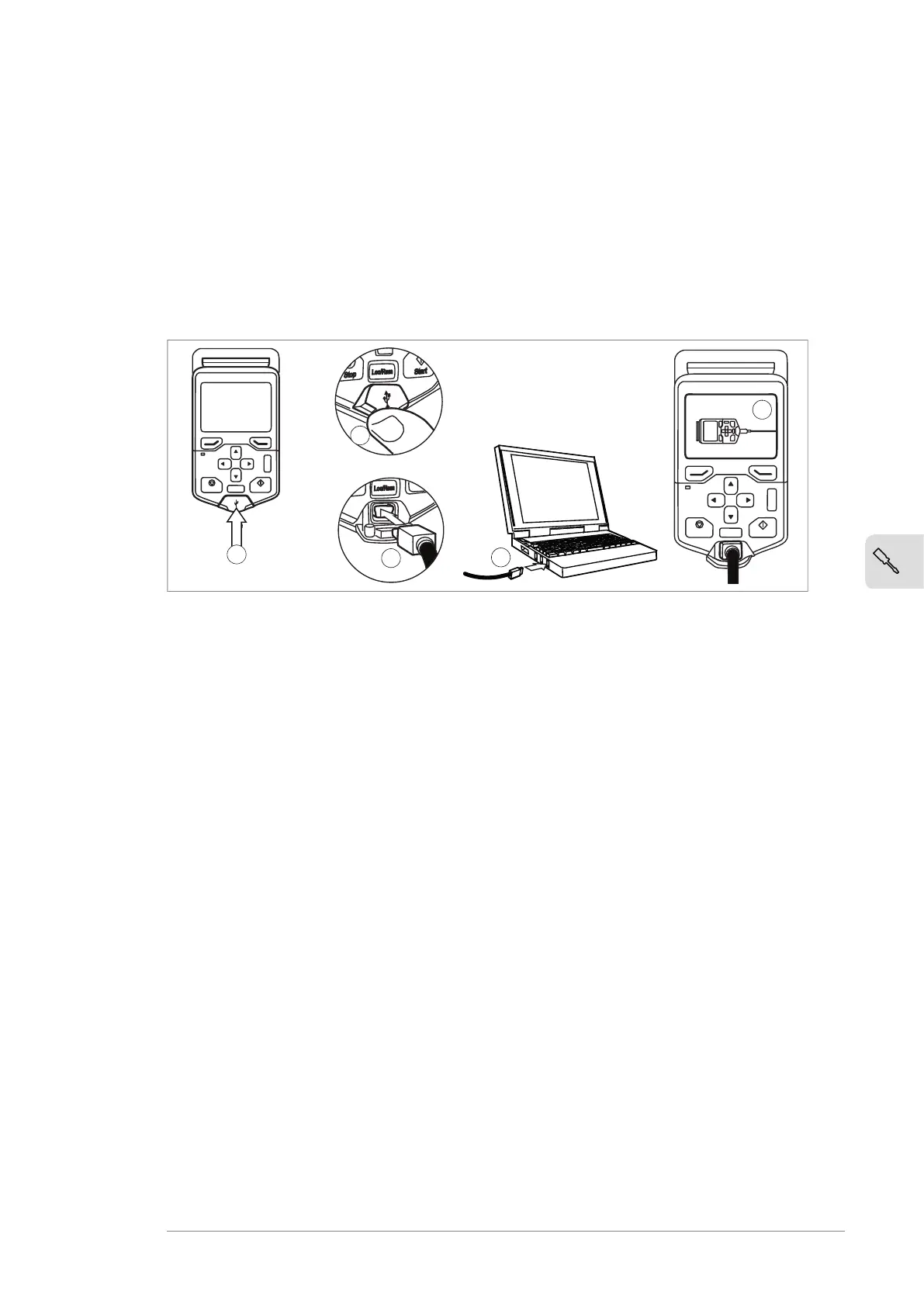
2. Remove the USB connector cover on the front of the control panel.
3. Connect an USB cable (Type A to Type Mini-B) between the USB connector on the
control panel (3a) and a free USB port on the PC (3b).
4. The panel will display an indication whenever the connection is active.
5. See the documentation of the PC tool for setup instructions.
?
Start
Stop
Loc/Rem
?
Start
Stop
Loc/Rem
USB connected
3a
4
3b
2
2
Panel bus (control of several units from one control panel)
One control panel (or PC) can be used to control several drives (or inverter units, supply
units etc.) by constructing a panel bus. This is done by daisy-chaining the panel
connections of the drives. Some drives have the necessary (twin) panel connectors in
the control panel holder; those that do not require the installation of an FDPI-02 module
(available separately). For further information, see the hardware description and
FDPI-02 diagnostics and panel interface user’s manual (3AUA0000113618 [English]).
The maximum allowed length of the cable chain is 100 m (328 ft).
1. Connect the panel to one drive using an Ethernet (for example Cat 5e) cable.
• Use Menu - Settings - Edit texts - Drive to give a descriptive name to the drive
• Use parameter 49.01* to assign the drive with a unique node ID number
• Set other parameters in group 49* if necessary
• Use parameter 49.06* to validate any changes.
*The parameter group is 149 with supply (line-side), brake or DC/DC converter
units.
Repeat the above for each drive.
2. With the panel connected to one unit, link the units using Ethernet cables.
3. Switch on the bus termination on the drive that is farthest from the control panel
in the chain.
• With drives that have the panel mounted on the front cover, move the
terminating switch into the outer position.
• With the FDPI-02 module: move termination switch S1 on the FDPI-02 module
into the TERMINATED position.
Electrical installation 73

 Loading...


