• DC busbar assembly to upper insulators (2 × M8): 9 N·m (6.6 lbf·ft)
• DC busbar assembly to lower insulators (2 × M10): 18 N·m (13.3 lbf·ft)
• Fuses to DC busbars: 50 N·m (37 lbf·ft) (Bussmann), 46 N·m (34 lbf·ft)
(Mersen/Ferraz-Shawmut)
• Module to cabinet frame (4 × M8): 22 N·m (16 lbf·ft)
• DC busbar assembly to module DC input (2 × M12): 70 N·m (52 lbf·ft)
2. Restore the original wiring (STO and control unit power supply whenever needed).
3. Set parameter 95.13 to 0 to disable the reduced run function.
4. If the Safe torque off (STO) function is in use, perform a validation test. See the
STO instructions.
Replacing DC fuses (frame R8i and multiples)
WARNING!
Obey the safety instructions given in ACS880 multidrives cabinets and
modules safety instructions (3AUA0000102301 [English]). If you ignore
the safety instructions, injury or death, or damage to the equipment
can occur.
If you are not a qualified electrical professional, do not do installation
or maintenance work.
WARNING!
Use the required personal protective equipment. Wear protective gloves and
long sleeves. Some parts have sharp edges.
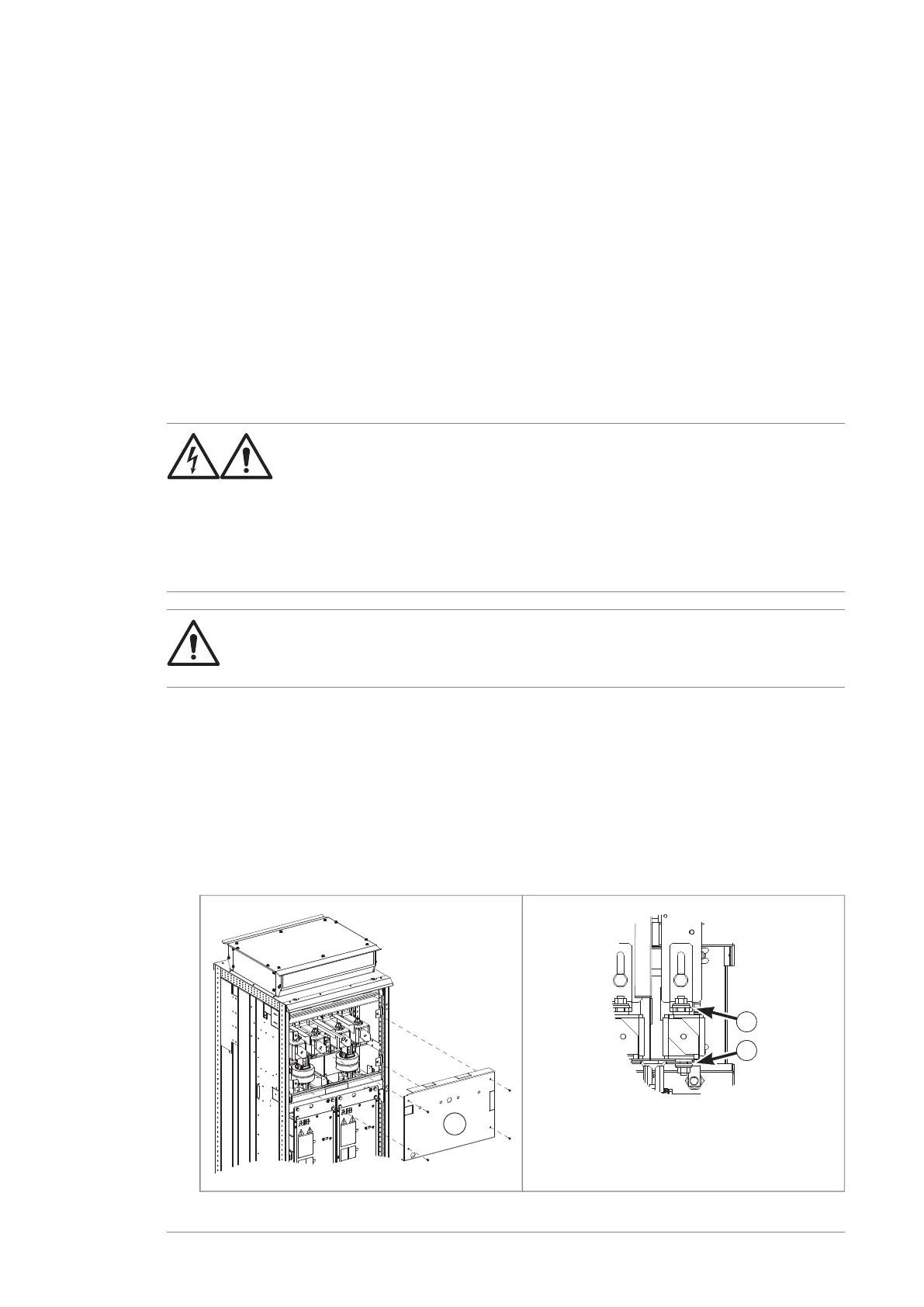
Note: The illustrations represent a frame 2×R8i inverter cubicle with option +F286 (DC
switch-disconnector). On units without +F286, the DC busbars are oriented differently,
but the procedure is otherwise the same unless noted.
1. Stop the drive and do the steps in section Electrical safety precautions (page 44)
before you start the work.
2. Remove the shroud (a) in front of the fuses.
3. Loosen the nuts (b) of the blown fuse.
Maintenance 135

 Loading...


