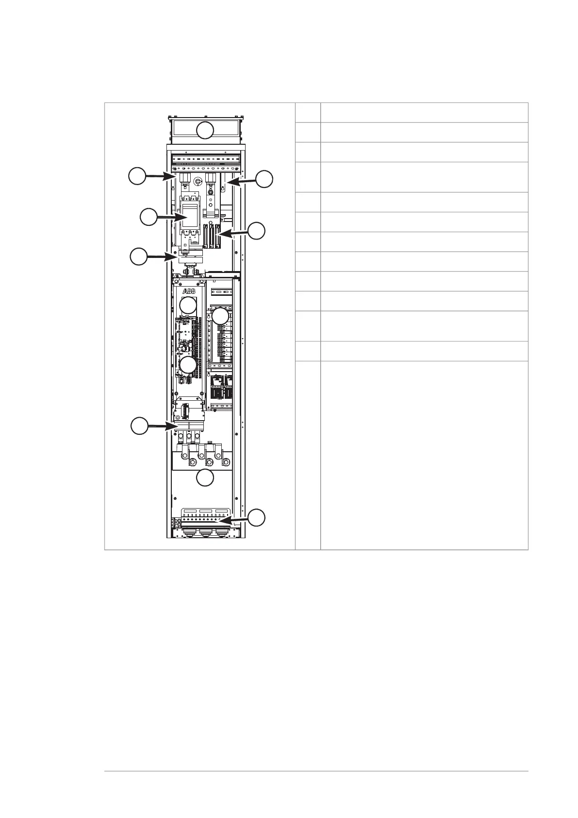
This illustration shows an example of a cubicle with an R6i/R7i inverter module.
ExplanationItem
Air outlet1
DC fuses2
DC switch-disconnector (behind DC fuses and
mounting plate) (optional)
3
Charging contactor (R7i only) (optional)4
Charging resistors (R7i only) (optional)5
Common mode filters6
Inverter module7
Inverter module cooling fan(s)8
Control unit9
Control voltage circuit components, installation
space for other equipment such as relays
10
Output busbars11
Cable entries12
Motor cabling
The motor cables are connected to the output busbars at the bottom of the cubicle.
For top exit, the depth of the cabinet is increased by 130 mm.
Operation principle and hardware description 27

 Loading...


