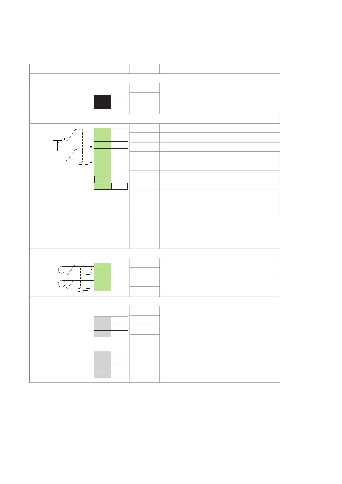
Default I/O diagram of the inverter control unit (ZCU)
DescriptionTermConnection
XPOW External power input
24 V DC, 2 A min. (without optional modules)
+24VI
GND
XAI Reference voltage and analog inputs
10 V DC,
R
L
1…10 kohm+VREF
+VREF
-VREF
AGND
AI1+
AI1-
AI2+
AI2-
1
2
3
4
5
6
7
AI2:I
AI2:U
AI1:I
AI1:U
-10 V DC,
R
L
1…10 kohm-VREF
GroundAGND
Speed reference
0(2)…10 V,
R
in
> 200 kohm
1)
AI1+
AI1-
By default not in use.
0(4)…20 mA,
R
in
= 100 ohm
1)
AI2+
AI2-
Current (I) / voltage (U) selection jumper for AI1
AI1
(ZCU-12)
J1
(ZCU-14)
Current (I) / voltage (U) selection jumper for AI2
AI2
(ZCU-12)
J2
(ZCU-14)
XAO Analog outputs
Motor speed rpmAO1
0…20 mA,
R
L
< 500 ohm
AGND
Motor current
0…20 mA,
R
L
< 500 ohm
AO2
AGND
XD2D Drive-to-drive link
Master/follower, drive-to-drive or embedded
fieldbus connection
2)
BZCU-12:
A
BGND
Shield
(ZCU-14
only)
ZCU-14:
Drive-to-drive link termination
2)
J3
80 Control units of the drive

 Loading...


