Connecting the emergency stop push buttons (option +Q951)
Connect external emergency stop push buttons (if any) according to the circuit
diagrams delivered with the drive.
Wiring the starter for auxiliary motor fan (options +M6xx)
Connect the power supply wires for the auxiliary motor fan to terminal blocks
X601…X605 according to the circuit diagrams delivered with the drive.
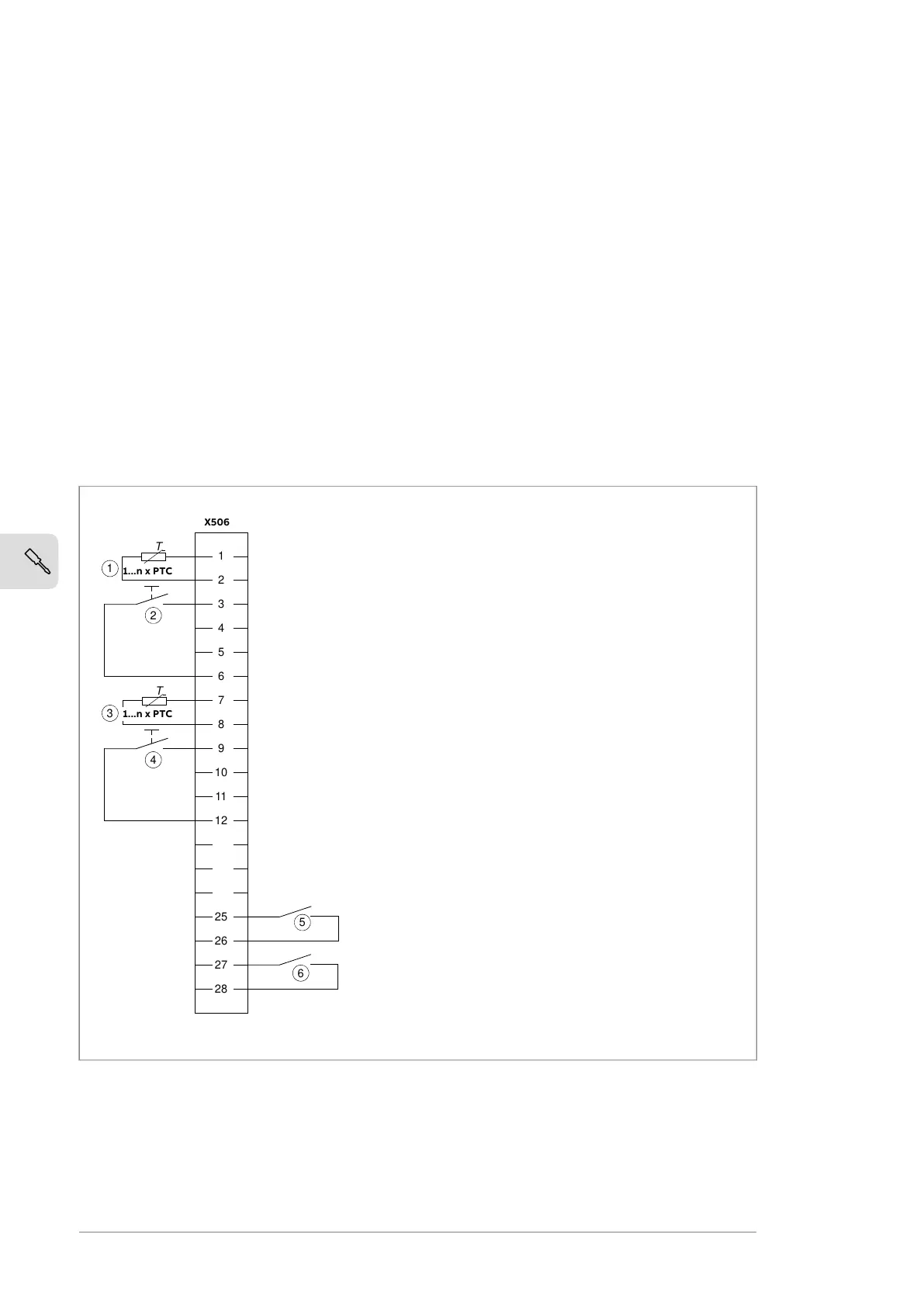
Wiring the PTC thermistor relay(s) (options +L505, +2L505, +L513 and +2L513)
The external wiring of option +2L505 and +2L513 (two thermistor relays) is shown
below. For example, one relay can be used to monitor the motor windings, the other
to monitor the bearings. The maximum contact load capacity is 250 V AC 10 A. For the
actual wiring, see the circuit diagram delivered with the drive. For instructions on
commissioning options +L513 and +2L513, see ATEX-certified motor thermal protection
functions for cabinet-built ACS880 drives (options +L513+Q971 and +L514+Q971) user's
manual (3AXD50000014979 [English]).
102 Electrical installation
Wiring the thermistor relay(s) (options +L505 and +2L505)
The external wiring of option +2L505 (two thermistor relays) is shown below. For example,
one relay can be used to monitor the motor windings, the other to monitor the bearings.
The maximum contact load capacity is 250 V AC 10 A. For the actual wiring, see the circuit
diagram delivered with the drive.
1
2
3
4
5
6
7
8
9
10
11
12
25
26
27
28
T
T
6
5
1
2
3
4
5
6
2
3
1
4
X506
1...n x PTC
1...n x PTC
PTC sensors monitored by relay K74.
R
G
=
R
1
+
R
2
+
R
N
< 1.5 kohm.
1
External reset for relay K74.
Note: With +L505 and +2L505, the terminals can be
bridged for automatic reset. However, this is not al-
lowed by ATEX regulations.
2
PTC sensors monitored by relay K75.
R
G
=
R
1
+
R
2
+
R
N
< 1.5 kohm.
3
External reset for relay K75.
Note: With +L505 and +2L505, the terminals can be
bridged for automatic reset. However, this is not al-
lowed by ATEX regulations.
4
Overheat indication from relay K74: overtemperature
= contact open.
5
Overheat indication from relay K75: overtemperature
= contact open.
6
Wiring the Pt100 relays (option +nL506)
External wiring of eight Pt100 sensor modules is shown below. Contact load capacity
250 V AC 10 A. For the actual wiring, see the circuit diagram delivered with the drive.
70 Electrical installation

 Loading...


