Connect the external power supply wires for the cabinet heater and lighting to terminal
block X300 at the back of the mounting plate.
104 Electrical installation
Powering the heating and lighting equipment (options +G300, +G301 and +G313)
See the circuit diagrams delivered with drive.
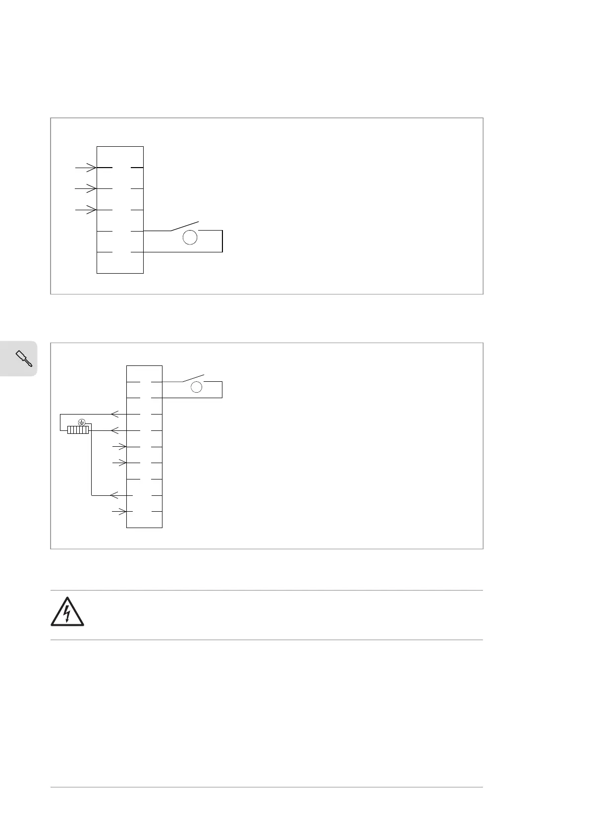
Connect the external power supply wires for the cabinet heater and lighting to terminal
block X300 at the back of the mounting plate.
Connect the motor heater wiring to terminal block X313 as shown below. Maximum
external power supply 16 A.
1
2
PE
4
5
N
L
X300
PE
1 Internal wiring of the cabinet heater: heater
off/fault = contact open.
1
1
2
3
4
5
6
7
PE2
PE1
N
L
N
L
X313
PE
1 Internal wiring of the motor space heater
supervision: heater off/fault = contact open.
1
Internal wiring of the cabinet heater: heater off/fault
= contact open.
1
Connect the motor heater wiring to terminal block X313 as shown below. Maximum
external power supply 16 A.
104 Electrical installation
Powering the heating and lighting equipment (options +G300, +G301 and +G313)
See the circuit diagrams delivered with drive.
Connect the external power supply wires for the cabinet heater and lighting to terminal
block X300 at the back of the mounting plate.
Connect the motor heater wiring to terminal block X313 as shown below. Maximum
external power supply 16 A.
1
2
PE
4
5
N
L
X300
PE
1 Internal wiring of the cabinet heater: heater
off/fault = contact open.
1
1
2
3
4
5
6
7
PE2
PE1
N
L
N
L
X313
PE
1 Internal wiring of the motor space heater
supervision: heater off/fault = contact open.
1
Internal wiring of the motor space heater supervision:
heater off/fault = contact open.
1
Connecting a PC
WARNING!
Do not connect the PC directly to the control panel connector of the control
unit. It can cause damage.
A PC (with, for example, the Drive composer PC tool) can be connected as follows:
72 Electrical installation

 Loading...


