■
Inverter module frame sizes R1i…R4i
General
The motor (output) cables are connected to either detachable or non-detachable screw
terminal blocks at the bottom of the cubicle. The modules have a built-in ZCU drive
control unit, which contains the basic I/Os and slots for optional I/O modules.
The modules have an internal capacitor precharge circuit.
External optional equipment is primarily installed on mounting plates in the same
cubicle.
Module layout examples
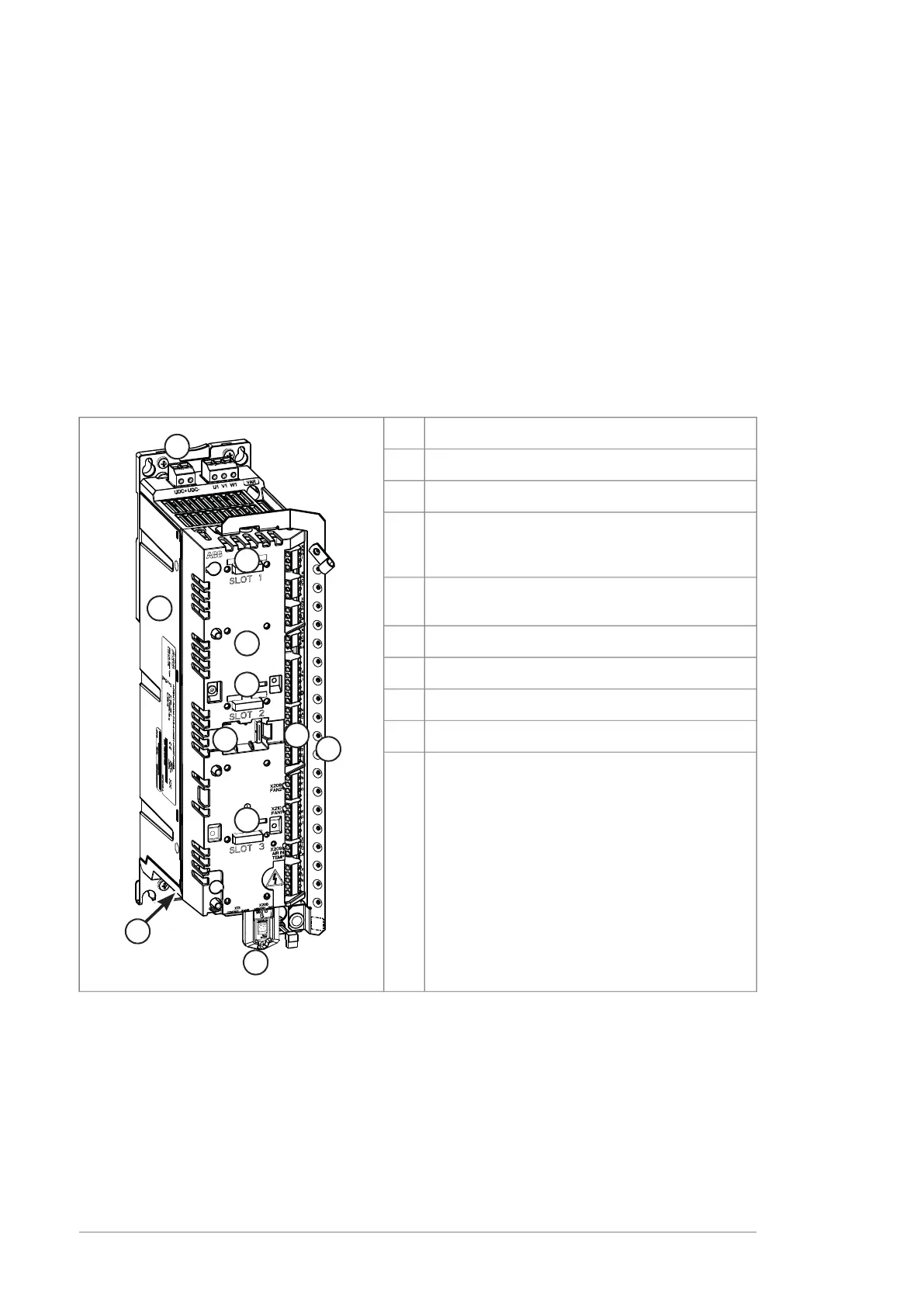
Frame R1i (Frame R2i has a similar layout)
ExplanationItem
Power unit1
DC (input) connections2
Motor (output) connection (obscured). This has
been wired to a separate terminal block in the
lower part of the cubicle.
3
ZCU-14 control unit mounted on top of the power
unit
4
Grounding/strain relief rail for control cables5
I/O terminal blocks6
3 slots for optional modules7
Memory unit8
Connection for FSO safety functions module9
18 Operation principle and hardware description

 Loading...


