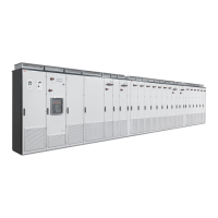
Each module has a dedicated DC switch-disconnector. When the switch-disconnector
is open, the door to that particular compartment can be opened. It is also allowable
to replace the module, its cooling fan, or its DC fuses.
The motor (output) connections for each module are located at the lower part of the
cubicle. The cubicle is equipped with cable entries at the floor.
This illustration shows an example of the layout with two R5i modules.
ExplanationItemCompartment (doors open)Compartment (doors closed)
Main DC switch-disconnector
handle for both modules in the cu-
bicle
1
Compartment for DC fuses
DC switch-disconnectors (with
fuses) for each individual module
2
Inverter modules3
Inverter control units4
Output connections5
Cable entries6
Operation principle and hardware description 25

 Loading...


