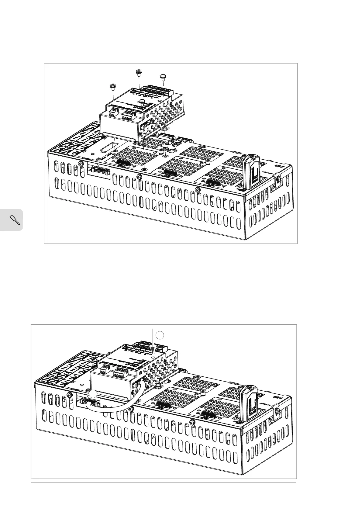
3. Attach the FSO module onto slot 3 of the BCU control unit [A41] with four screws.
4. Torque the FSO module electronics grounding screw to 0.8 N·m (7.1 lbf·in).
Note: The screw tightens the connections and grounds the module. It is essential
for fulfilling the EMC requirements and for proper operation of the module.
5. Connect the FSO module data cable between FSO connector X110 and BCU
connector X12.
6. To complete the installation, refer to the instructions in the applicable FSO module
user's manual.
64 Electrical installation

 Loading...


