Planning the electrical installation
28
3ADW000194R0611 DCS800 Hardware Manual f us
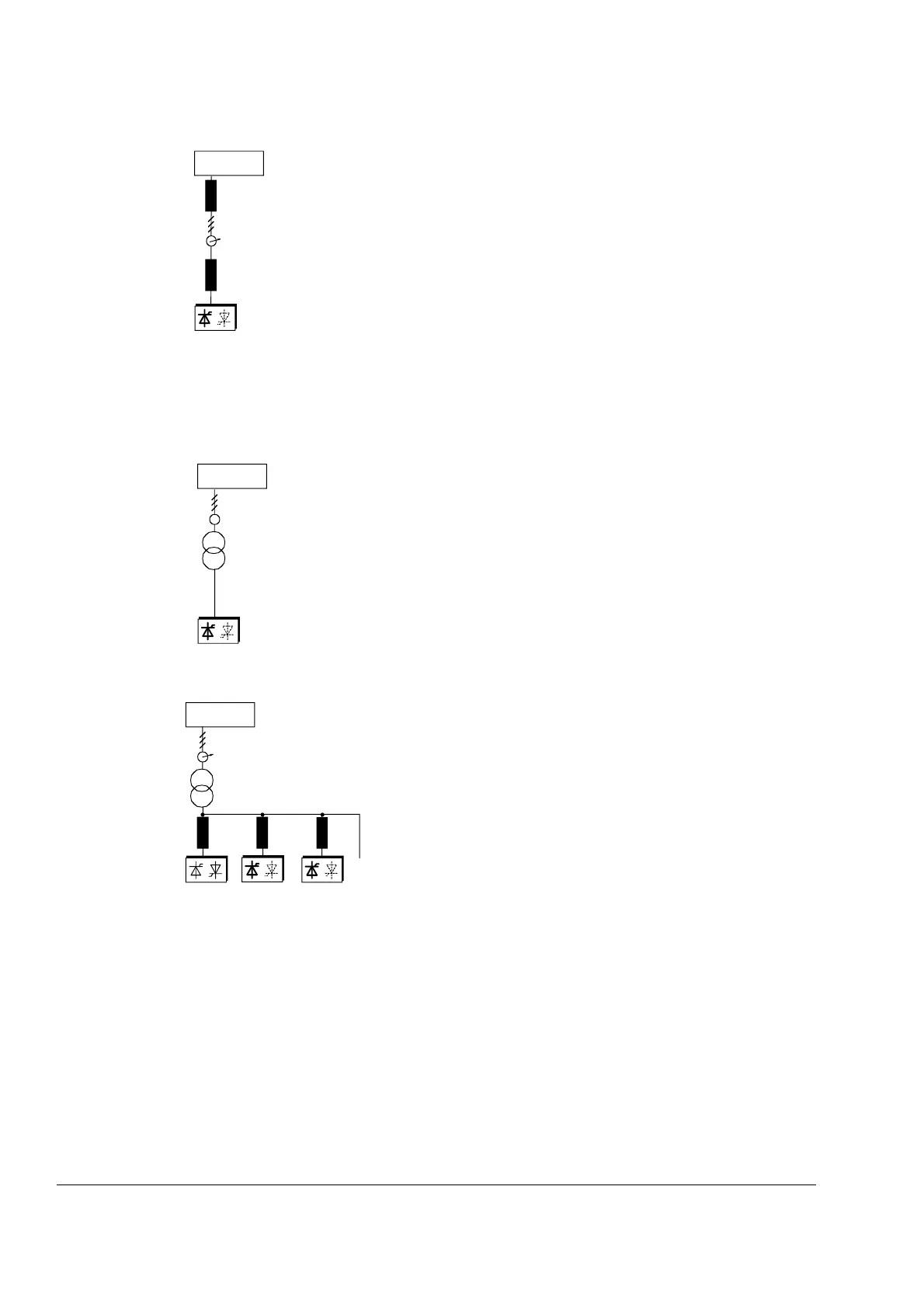
Configuration B
If special requirements have to be met at the PCC (standards like EN
61 800-3, DC and AC drives at the same line, etc), different criteria
must be applied for selecting a line reactor. These requirements are
often defined as a voltage dip in percent of the nominal supply
voltage.
The combined impedance of Z
Line
and Z
L1
constitute the total series
impedance of the installation. The ratio between the line impedance
and the line reactor impedance determines the voltage dip at the
connecting point. In such cases line chokes with an impedance
around 4% are often used.
Example calculation with U
k Line
=1%;
U
k L1
=4%; Voltage Dip = Z
Line
/(Z
Line
+Z
L1
)=20%. Detailed calculation
see Technical Guide.
Configuration C
If an isolation transformer is used, it is possible to comply with certain
connecting conditions per Configuration B without using an additional
line reactor. The condition described in Configuration A will then
likewise be satisfied, since the u
k
is >1 %.
Configuration C1
If 2 or more converters should be supplied by one
transformer the final configuration depends on the
number of drives in use and their power capability.
Configuration A or B has to be used which are based on
commutation chokes, if the drive system consists of any
of the converters (D1, D2, D3, D4, D5, D6, D7). In case
only two converters type D7 are involved no
commutation chokes are necessary because the design
of these converters is adapted to that wiring.
With reference to the power converter:
The line reactors listed in table below
• have been sized to the units nominal current
• are independent of converter's voltage classification; at some converter types the
same line choke is used up to 690 V line voltage
• are based on a duty cycle
• can be used for DCS800 as armature converter as well as field converter but
rated line choke current must be considered.
You will find further information in publication:
Technical Guide chapter: Line reactors
(P
cc
)
PCC
Line
L
Line
L
L1
(P
cc
)
Line
PCC
(P
cc
)
....
Netzdr_g.dsf
L
L1
L
L1
L
L1
PCC
Line