Planning the electrical installation
40
3ADW000194R0611 DCS800 Hardware Manual f us
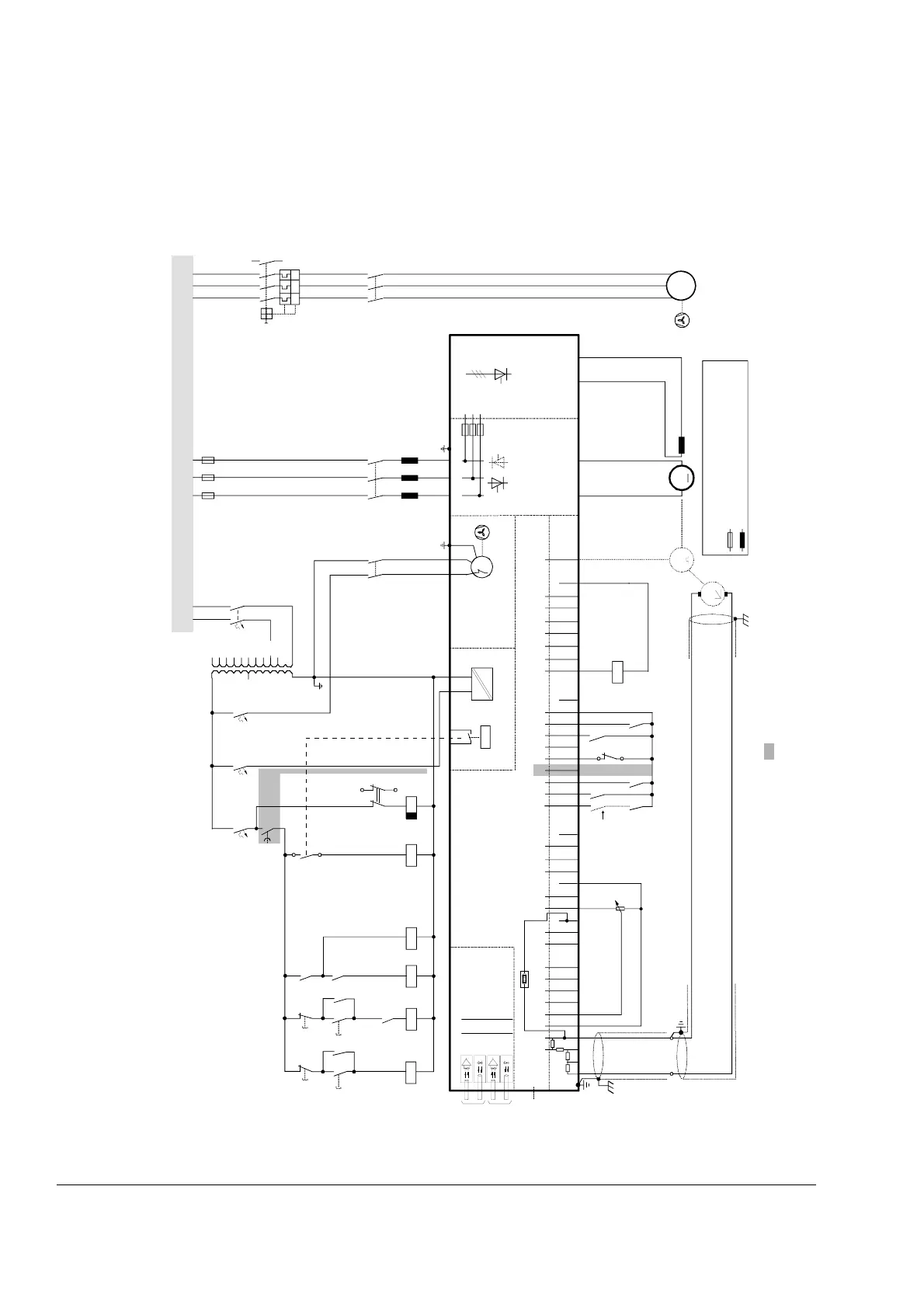
Converters D1...D4 drive configuration using ’on board’ field exciter
Wiring the drive according to this diagram offers the highest degree of monitoring
functions done by the drive.
further information see drawing at page 43
IN3
OUT3
IN1
OUT1
V5
V6
V1
V2
X96:
DO8
12 X99:12 X2:1 23
U1 W1V1 PE
K1
F6
K20
K21K20 K1
X96:1
X96:2
L1 L2 L3
F1
M
~
F2
3
4
1
2
T2
690V
660V
600V
575V
525V
500V
450V
415V
400V
380V
115V
230V
K15
K15
S1
1
2
K6 K8
K10
K21
X33
C 1 D 1
AITAC AI1
AI2 AI3
AI4
+10V -10V AO1 AO2 IACT DI1 DI2 DI3 DI4 DI5 DI6 DI7 DI8 +24V DO1 DO2 DO3 DO4 DO5 DO6 DO7
____
_
++++
+
T
T
M
0V
0V0V0V0V
X3:12345678910X4:12345678910X6:12345678910
X7:
12 34 56 7 8 1...10
X5:
+
_
+
_
K1
K20
K21
K6
K8
1
2
S1
K10
S1
56
2
46
1
35
K6
F5
1
2
F8
1
2
F7
1
2
2
1
4
3
6
5
F6
I > I > I >
13
14
U
V
W
M
3~
K1
135
246
L1
1
2
3
4
K8
13
14
X10:
F+ F-
21
L1 L2 L1 L2 L3
DCS8_ans_1_1d.dsf
DCS800
*
PIN-4
Communication
board (COM-8x)
Control board (CON-4)
Power supply
Converter
module
ON
OFF STOP
START
EMER.
STOP
'on board' field exciter
see section fan connection
the polarities are shown for motoring
if there are intermediate terminals
e.g. Pressure
switch at D7
module
Voltage levels
see description
* set by
[50.12],
[50.13]
Legend
fuse
reactor
Line reactor
Motor fan