Mechanical installation
25
3ADW000194R0611 DCS800 Hardware Manual f us
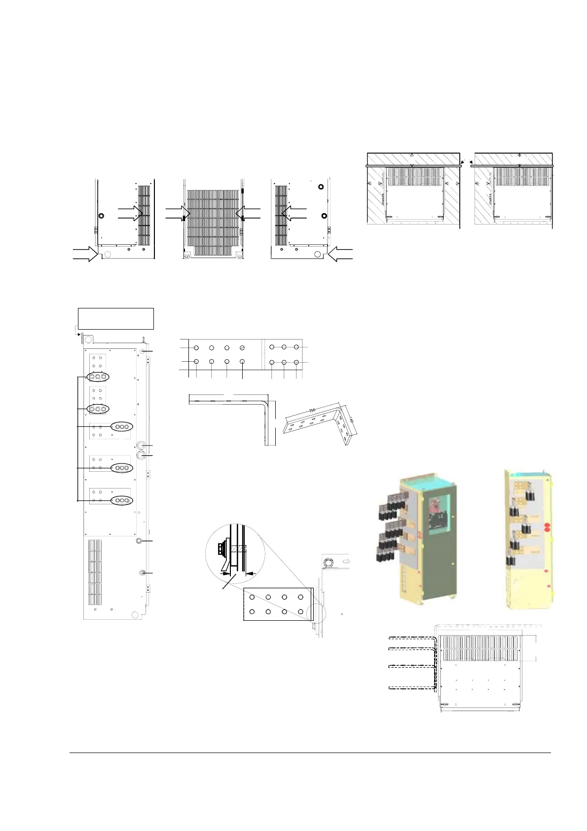
Mounting the converter module D6 inside an enclosure
Cooling air entry
The cooling fan takes the air from the backside, both sides and from the area
underneath the converter module.
Free space around the converter module
optimum compromise
Cooling air outlet
To avoid circulating air inside the enclosure it is recom-
mended to make sure the exhaust air leaves the enclo-
sure.
Cable entries Power cable connection
The power cable connection is performed via Terminal
option 01 for D6. This option consists of one right
angle copper busbar. The mechanical details are
shown by the figure below.
The figure below gives an example, how the right angle
busbars can be mounted in case all cable connections
are still made at the left side of the converter module.
This results in four layers for the power cables.
In case the AC or DC connection or perhaps both of
them have to be made at the right side of the converter
module use the space behind the converter and move
the power terminals via a right angle busbar up to that
point where the final connection is most suitable. In this
case the busbars need to be fixed at the cubicle /
enclosure, not at the converter module! The figures
below give a rough example, how a right side connec-
tion can be made.
When mounting the right angle busbars or connecting
cables directly please make sure the correct bolts are
used. The converter module is equipped with a thread
hole at left side. Because of that the length of the
remaining threads is limited to 35 mm (see drawing
below).
air flow
air flow
air flow
air flow
air flow
air flow
A6_li_air_inlet.dsf
View from: the right side the back the left side
5050
~ 100
50
TMR
~ 100
Top view
Top view
C
D
U
V
W
A6_li_air_inlet_c.dsf
do not unscrew these bolts !
electronics power supplycontrol cables
pressure
switch
converter fan
(left and right side)
the module must be fixed
at the upper side with
TMR (Top Mounting Rail)
100
72.2
21.8
0
0
25
75
125
175
272
312
352
372
25
75
Ø14
250
140
A6_cable_term_busb.dsf
max.
35mm
468.2
136
Example right side connection