Electrical installation
59
3ADW000194R0611 DCS800 Hardware Manual f us
Pulse encoder connection
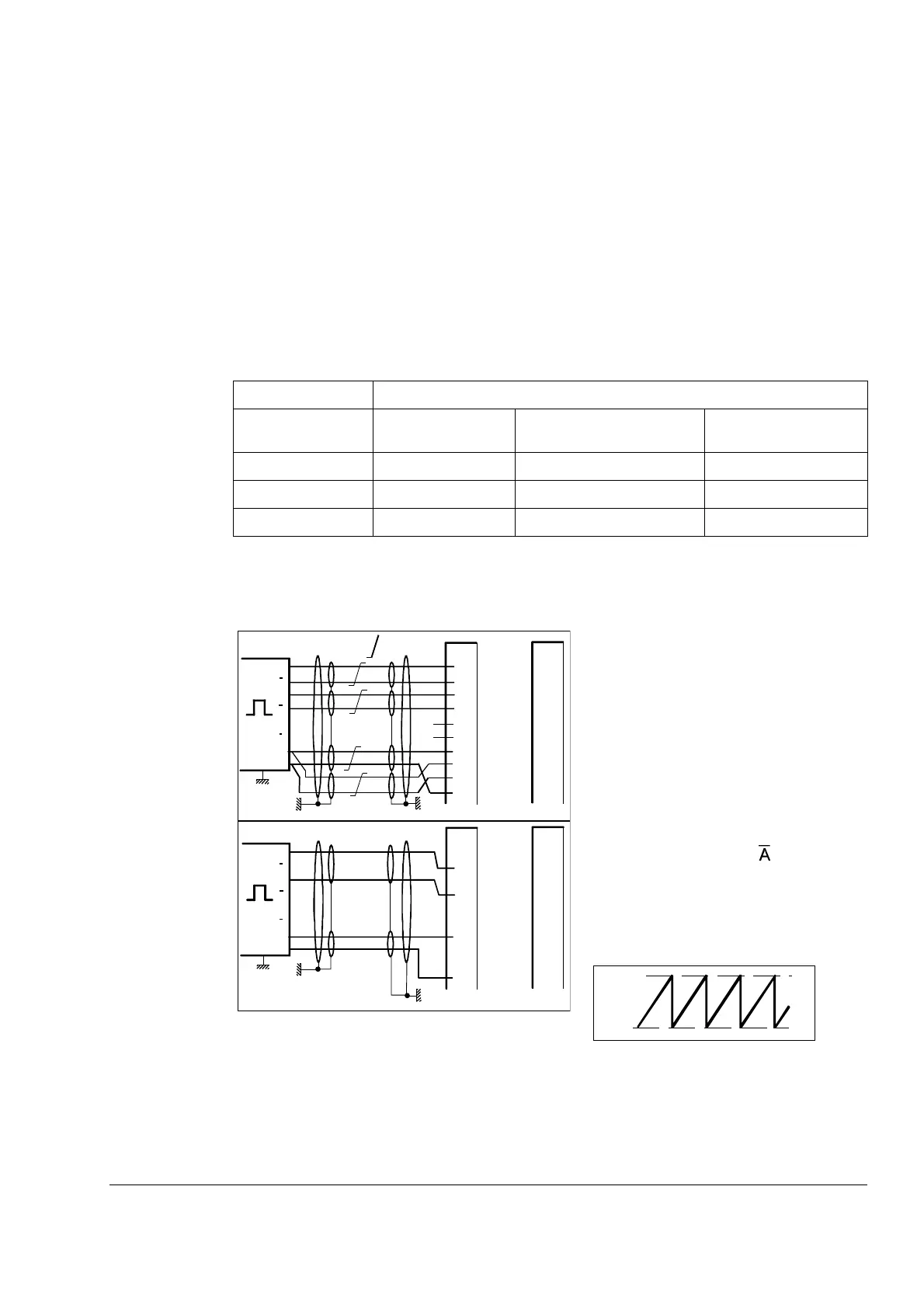
Connecting a pulse encoder to the DCS800 converter
The connection diagram for a pulse encoder to the electronics of a DCS converter is
quite similar, if the SDCS-CON-4 or the SDCS-IOB-3 is used. The basic difference
between these 2 boards is the galvanically isolated circuit and pulse receivers via
opto coupler on the SDCS-IOB-3 board.
Power supply for incremental encoder
SDCS-CON-4 and SDCS-IOB-3 board have jumpers to select a supply voltage. V17
LED on SDCS-IOB-3 indicates supply is OK.
Sense feedback connection is recommended when power supply level for
differential pulse encoder is 5 V. The wiring is shown on figure below.
Commissioning hint
Note:
If the drive’s measured direction of
rotation is wrong or does not
correspond to measured EMF speed,
the SPEEDFB fault may appear
during start-up. If necessary correct
by exchanging the field connection
If with a positive reference the
position signal 3.07 or 3.08 signal
does not look like the illustration
below, then tracks A & must be
exchanged with inverted signals. For
single-ended encoders Tracks A and
B must be exchanged.
.
Hardware configuration
Encoder supply SDCS-CON-4
supplied by PIN-4
SDCS-CON-4
supplied by POW-1/POW-4
SDCS-IOB-3
5 V sense controlled sense controlled sense controlled
12 V - no sense sense controlled
24 V no sense no sense no sense
A
A
B
B
Z
Z
+U
0V
X5:2
X5:1
X5:4
X5:3
X5:6
X5:5
IOB-3
X5:7
X5:10
X5:8
X5:9
X5:2
X5:1
X5:4
X5:3
X5:6
X5:5
CON-4
X5:10
X5:7
X5:9
X5:8
GND
ChA+
ChA-
ChB+
ChB-
ChZ+
ChZ-
A
A
B
B
Z
Z
+U
0V
X5:2
X5:1
X5:4
X5:3
X5:6
X5:5
IOB-3
X5:7
X5:10
X5:8
X5:9
X5:2
X5:1
X5:4
X5:3
X5:6
X5:5
CON-4
X5:10
X5:7
X5:9
X5:8
GND
ChA+
ChA-
ChB+
ChB-
ChZ+
ChZ-
IOB3x3_g.dsf
DIFFERENTIAL
Power source
Sense power
Sense GND
Power source
= twisted
pair
SINGLE-ENDED
0
65535
Forward