Planning the electrical installation
41
3ADW000194R0611 DCS800 Hardware Manual f us
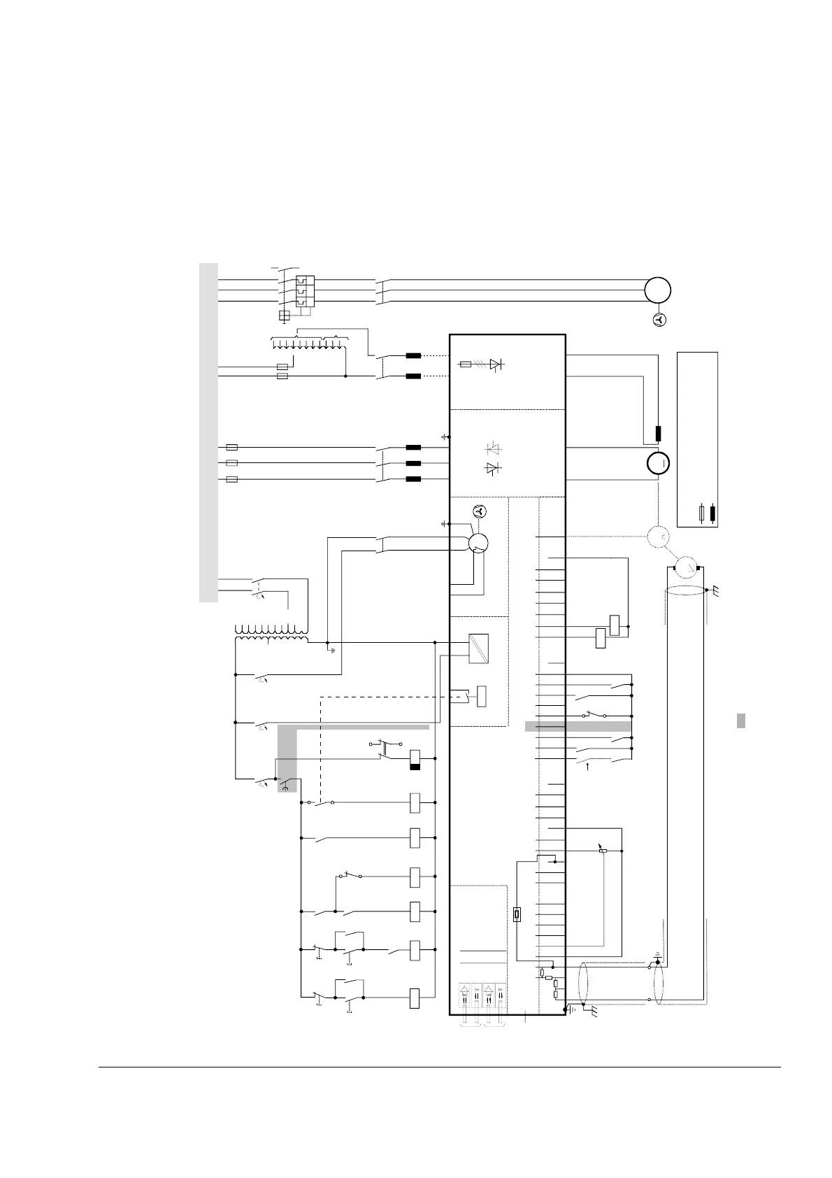
Converters D5 drive configuration using ’FEX-425-Int’ field exciter
Wiring the drive according to this diagram gives the most flexibility and offers the
highest degree of monitoring functions done by the drive. Field converters FEX-425-
Int are equipped with their own synchronization and can be supplied from an
independent net. FEX-425-Int can be supplied separate max. 500 V (3-phase), or 2-
phase.
further information see drawing at page 43
IN3
OUT3
IN1
OUT1
V5
V6
V1
V2
X96:
DO8
12 X99:12 X2:45 X2:1 23
U1 W1V1 PE
K1
F6
K20
K21K20 K3 K1
X96:1
X96:2
L1 L2 L3
F1
F3
K3
13
24
M
~
T3
F2
3
4
1
2
T2
690V
660V
600V
575V
525V
500V
450V
415V
400V
380V
115V
230V
K15
K15
S1
1
2
K6 K8
X2:4
X2:5
K11
K10
K21
500V
460V
415V
400V
365V
350V
265V
250V
90V
60V
30V
X33
C 1 D 1
AITAC AI1
AI2 AI3
AI4
+10V -10V AO1 AO2 IACT DI1 DI2 DI3 DI4 DI5 DI6 DI7 DI8 +24V DO1 DO2 DO3 DO4 DO5 DO6 DO7
____
_
++++
+
T
T
M
0V
0V0V0V0V
X3: 1 2 3 4 5 6 7 8 9 10 X4: 1 2 3 4 5 6 7 8 9 10 X6: 1 2 3 4 5 6 7 8 9 10
X7:
12345678 1...10
X5:
+
_
+
_
K1
K20
K21
K6
K8
1
2
S1
K11
K10
S1
56
2
46
1
35
K6
F5
1
2
F8
1
2
F7
1
2
2
1
4
3
6
5
F6
I > I > I >
13
14
U
V
W
M
3~
K1
135
246
L1
1
2
3
4
K8
13
14
UW
L3
X100: 1 3
+
_
L1 L2 NL1 L1L2L3
DCS8_ans_1_2c.dsf
DCS800
*
Communication
board (COM-8x)
Control board (CON-4)
Power supply
(POW-4)
Converter
module
ON
OFF STOP
START
EMER.
STOP
Field exciter unit
FEX-425-Int
depending on the unit type
an other configuration is possible
the polarities are shown for motoring
if there are intermediate terminals
e.g. Pressure
switch at D7
module
Voltage levels
see description
* set by
[50.12],
[50.13]
Legend
fuse
reactor