Planning the electrical installation
46
3ADW000194R0611 DCS800 Hardware Manual f us
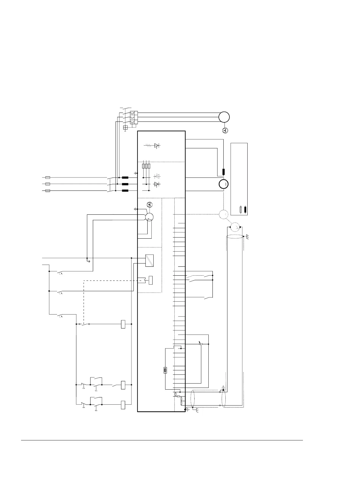
Drive configuration with reduced components
Converters D1...D4 (400...500 V) using ’on board’ field exciters
Converters D5 using FEX-425-Int field exciter, but externally supplied
Wiring the drive according to this diagram gives the same control performance, but a lower degree of
flexibility. Dynamic Braking keeps the main contactor K1 in state ON during braking.
Selection of components: The wiring diagram is valid for a DCS800 converter construction type D1...D4 ≤ 525 V and D5
≤ 500 V. The ’on board’ field exciter (D1...D4) can be used at line voltages up to 525 V and will give field currents up to 6 /
15 / 20 / 25 A. For higher field currents, use the next larger field supply units DCF803/804 or a 3-phase field supply DCS800.
* D1-D4: On board field exciter (PIN-4)
D5: FEX-425-Int field exciter, supplied external
X96:
DO8
1 2 X99: 1 2 X2: 4 5 X2: 1 2 3
U1 W1V1 PE
K1
K20
K21K20 K1
X96:1
X96:2
L1 L2 L3
400V 50Hz
F1
M
~
K21
C 1 D 1
AITAC AI1
AI2 AI3
AI4
+10V -10V AO1 AO2 IACT DI1 DI2 DI3 DI4 DI5 DI6 DI7 DI8 +24V DO1 DO2 DO3 DO4 DO5 DO6 DO7
____
_
++++
+
T
T
M
0V
0V0V0V0V
X3: 1 2 3 4 5 6 7 8 9 10 X4: 1 2 3 4 5 6 7 8 9 10 X6: 1 2 3 4 5 6 7 8 9 10
X7:
12345678 1...10
X5:
+
_
+
_
K1
K20
K21
S1
45
F5
1
2
F8
1
2
F7
1
2
K1
135
246
L1
X1: 5 3
+
_
L1 MP
2
1
4
3
6
5
F6
I > I > I >
13
14
U
V
W
M
3~
DCS8_ans_2b.dsf
*
Control board (CON-4)
Power supply
(PIN-4)
DCS800
Converter
module
ON
OFF STOP
START
Field exciter unit
(PIN-4) On board
depending on the unit type
another configuration is possible
the polarities are shown for motor operation
if there are intermediate terminals
*
Aux. supply
* set by
[50.12],
[50.13]
Legend
fuse
reactor