Technical data
79
3ADW000194R0611 DCS800 Hardware Manual f us
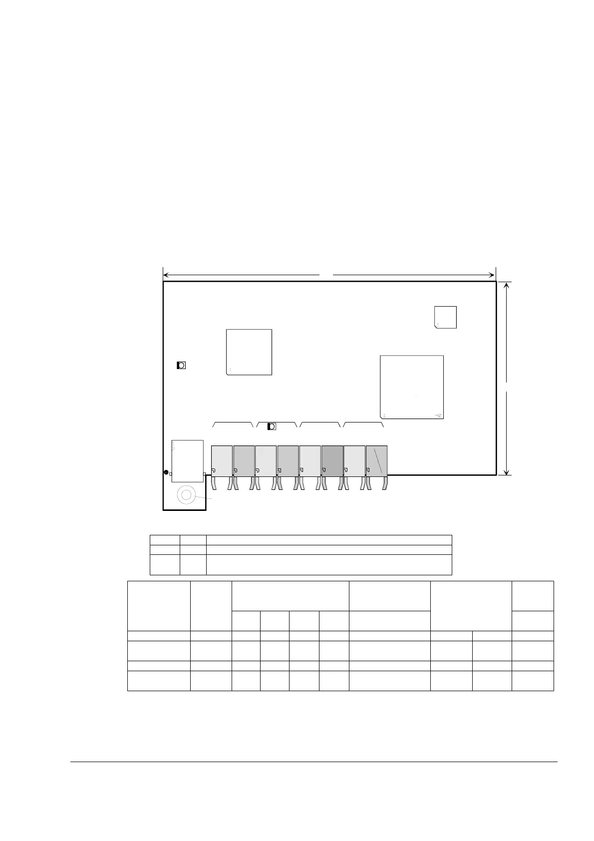
Interface Board SDCS-COM-8
This board must be used together with a DCS800 to provide same serial communication DDCS options
as ACS800.
Furthermore the board is equipped with four optical channels (max. data transmission speed is 4 Mb for
each optical channel):
• Channel 0 is used to communicate data from the overriding control (FCI, APC2, AC800M, Nxxx-xx
(adapter modules for fieldbus), AC80) or via adapter modules from other controllers) to the
DCS800-drive.
• Channel 1 is used for DDCS I/O extension. AIMA-01 board see separate documentation.
• Channel 2 (Master-Follower) is used to operate two or more drives dependent on each other.
Channel 3 is prepared to connect the PC tool for commissioning and maintenance (DriveWindow).
• Connector X19 is used for CDP 312 panel as well as interface board NDPI.
Explanation of LEDs on SDCS-COM-8
Color of optical components:
5 Mb -> blue driver current maximum 30 mA
Remark: Only channels with the same components (e.g. 10 Mb component) may be connected to
each other.
LED color Meaning
V6 green 5 V supply ok
V1 red blinking: boot procedure
permanent: SDCS-COM-8 fault
Type Revision optical components Channel 0 used for max. driver current Cunduc-
tive sup-
port
Ch 0
PLC
Ch 1
I/O
Ch 2
M/F
Ch 3
DW
SDCS-COM-81 from D...F 10 Mb 5 Mb 10 Mb 10 Mb other interfaces Ch 0, 2, 3 50 mA
SDCS-COM-82 from D...F 5 Mb 5 Mb 10 Mb 10 Mb Fieldbus adapter
modules Nxxx-xx
Ch 2, 3 50 mA
SDCS-COM-81 from G... 10 Mb 5 Mb 10 Mb 10 Mb other interfaces Ch 0, 2, 3 50 mA x
SDCS-COM-82 from G... 5 Mb 5 Mb 10 Mb 10 Mb Fieldbus adapter
modules Nxxx-xx
Ch 2, 3 50 mA x
148
86
D200
D400
D100
SDCS-COM-8
V1
V6
X19
CH 0
TxD
RxD
CH 1
TxD
RxD
CH 2
TxD
RxD
CH 3
TxD
RxD
COM_8_layout_b.dsf
grey
grey
grey
grey
dark
grey
dark
grey
d
a
r
k
g
r
e
y
b
l
u
e
blue
conductive support