Technical data
85
3ADW000194R0611 DCS800 Hardware Manual f us
Digital I/O board SDCS-IOB-2
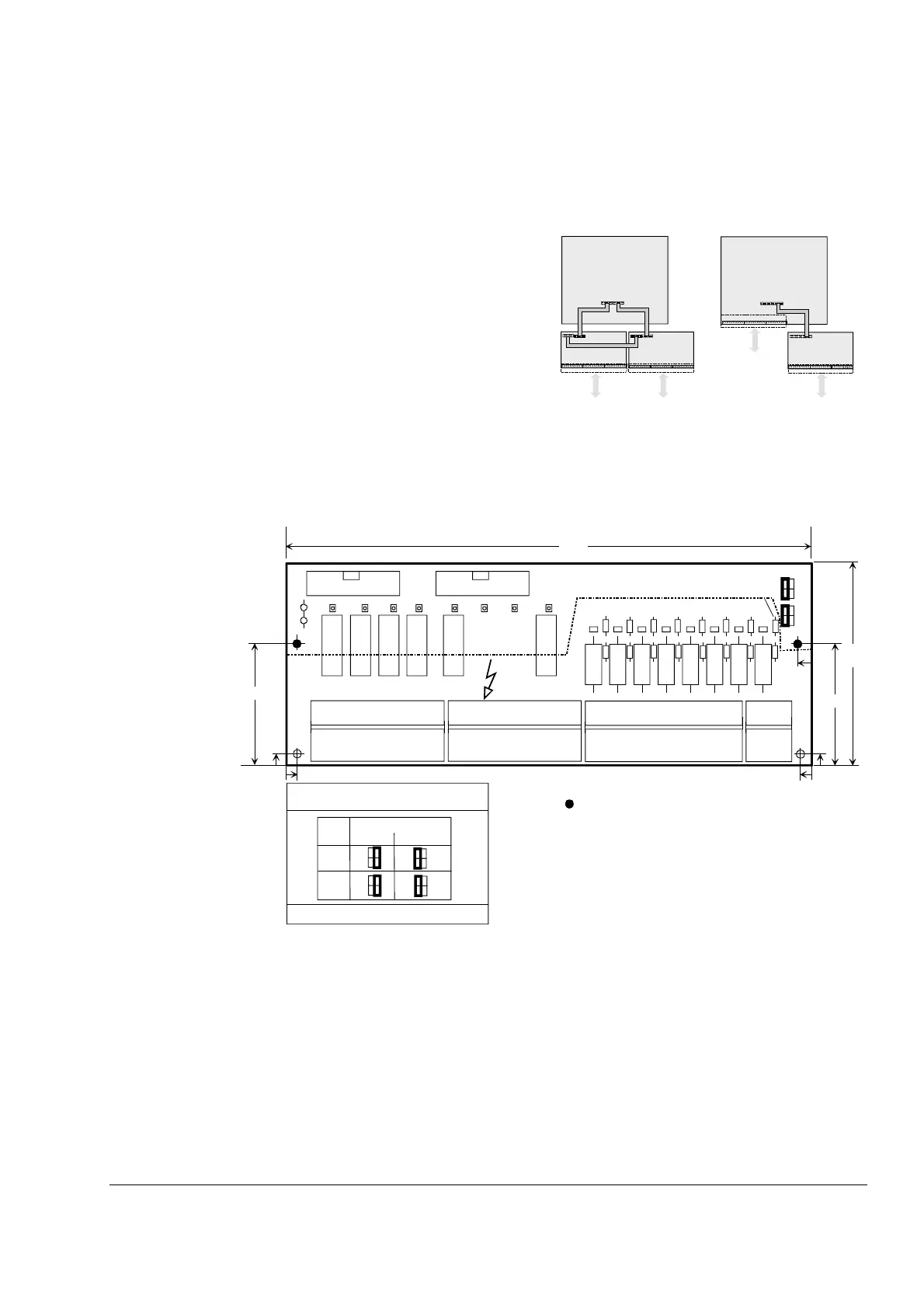
Layout and jumper settings of the SDCS-IOB-2x board
There is a card holder available as option for fastening the SDCS-IOB-2 board. For more information
see chapter Dimensional drawings.
As described at the beginning of the chapter, there are
various options for configuring the inputs/outputs.
The board IOB-2x has 8 digital inputs and 8 digital
outputs.
There are three different types existing, which differ at
the input voltage level:
SDCS-IOB-21 24...48V DC
SDCS-IOB-22 115 V AC
SDCS-IOB-23 230 V AC
The inputs are filtered and galvanically isolated by
using optocouplers. Inputs can form two galvanically
separated groups by using either X7:1 or X7:2.
If these boards are in use, they have to be mounted
outside the DCS module. They must be mounted in a
way, that the conductive supports have a good con-
nection to ground of the installation.
I/O via SDCS-IOB-2x / IOB-3 and SDCS-CON-4
The cable length between X1:/X1: and X2:/X2:
is max. 1.7 m (D1...D4 converters)
is max. 4 m screened (required for D7 converters)
between X1:/X3: is max. 0.5 m because of EMC rea-
sons.
See chapter Other cables.
X3: X4: X5:
X2: X1:
SDCS-CON-4
X3: X1:
SDCS-IOB-2
X2:
SDCS-IOB-3
X2:
SDCS-CON-4
X1:
SDCS-IOB-2
X1:
X1:
X3:
(
) ?
S8
S7
R1
SDCS-IOB-2x
DI1
R2 R3 R4 R5 R6 R7
R8
W13
W11
W9
W7
W5
W3
W1
W2
W4
W6
W8
W10
W12
W14
W15
W16
X6X5
X4
X1X3
K1 K2 K3 K4 K5 K8
DI2 DI3 DI4 DI5 DI6 DI7 DI8
DO1
DO2
DO3
DO4
DO5
DO6 DO7
DO8
1
1
1
X7
1
233.5
97.5
5
4
2ms
S7
*
10ms
DI 7
S8 *
DI 8
*
4 *
70
1
2
4
3
1
2
4
3
1
2
4
3
1
2
4
3
1
2
4
3
1
2
4
3
5
70
4
W100 **
iob2x1_d.dsf
time constant
Jumper coding
default value
input
supports are conductive
diameter of all supports: 4.3 mm
* this dimension may vary (4/5 mm)
depending on revision
Line potential !
** W100 as printed circuit