Electrical installation
60
3ADW000194R0611 DCS800 Hardware Manual f us
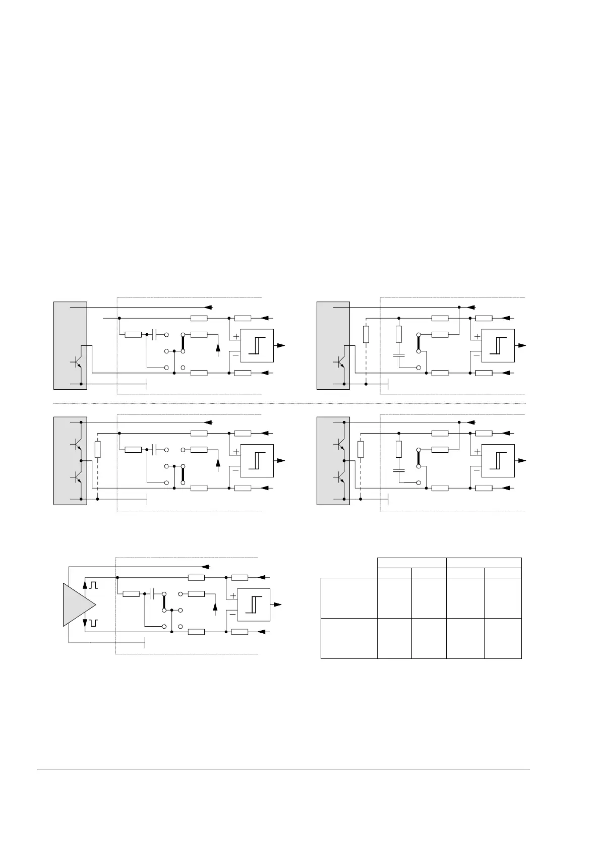
Pulse encoder receiver
Two different incremental encoder connections are available.
-differential connection; pulse encoders generating either voltage or current signals
can be used
-single-ended (push pull) connection; voltage signals
Restrictions using jumper S4 (CON-4): or S10 (IOB-3): depending on the board
Line termination via S4/S10 should not be used at 12 V or 24 V encoders, because
of the power consumption taken from the encoder. If a pulse encoder with a build in
current source is used a burden resistor of 120 Ω is activated via jumper S10: 1-2 on
SDCS-IOB-3 a.s.o.
Pulse encoder connection principles
In case of a single ended 5 V encoder the jumpers S4 / S10 will be set to a neutral position. To get a threshold lower than 5 V each
terminal X5:2 / X5:4 / X5:6 must be connected via a resistor R to GND.
In any case, if SDCS-IOB-3 is used, see required settings of SDCS-CON-4
board
1k0 4k7
1k0 4k7
+5V
121
Ω
100 nF
10k
+24V
+5V
0V / GND
X5:1
X5:2
X5:10
X5:7
6
5
4
3
2
1
S10
1k0 4k7
1k0 4k7
+5V
121
Ω
100 nF
10k
+5V
0V
+5V or +24V
X5:1
X5:2
X5:7
X5:10
3
2
1
S4
R
2k2
1k0 4k7
1k0 4k7
+5V
121
Ω
100 nF
10k
+24V
+5V
0V / GND
X5:1
X5:2
X5:10
X5:7
S10
6
5
4
3
2
1
2k2
R
2k2
1k0 4k7
1k0 4k7
+5V
121
Ω
100 nF
10k
+5V
0V
+5V or +24V
X5:1
X5:2
X5:7
X5:10
3
2
1
S4
R
encoder input_a.dsf
ENCODER CHANNEL A
SDCS
-IOB-3
ENCODER INPUT
A
ENCODER CHANNEL A
ENCODER CHANNEL A
SDCS
-IOB-3
ENCODER INPUT
A
ENCODER CHANNEL A
single ended
open collector
single ended
push pull
SDCS
-CON-4
ENCODER INPUT
A
SDCS
-CON-4
ENCODER INPUT
A
+5V or +12V or +24V
+5V or +12V or +24V
CON-4 IOB-3
5 V 12/24 V 5 V 12/24 V
differential
voltage source
S4
1-2
4-5
7-8
S4
3=park
6=park
9=park
S10
2-3
8-9
14-15
S10
4-5
10-11
16-17
differential
current source
--
S10
1-2
7-8
13-14
-
1k0 4k7
1k0 4k7
+5V
121 Ω
100 nF
10k
+24V
+5V
0V / GND
+5V
X5:1
X5:2
X5:10
X5:7
S10
6
5
4
3
2
1
ENCODER CHANNEL A
SDCS
-IOB-3
ENCODER INPUT
A
differential