Technical data
94
3ADW000194R0611 DCS800 Hardware Manual f us
Power Interface SDCS-PIN-46/SDCS-PIN-48/SDCS-PIN-5x
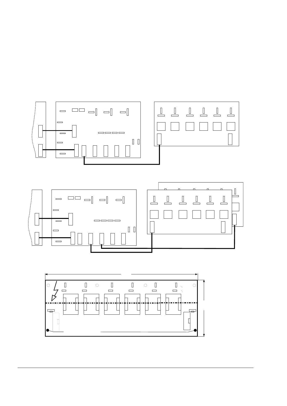
The Power Interface of DCS converter modules model D5/D6/D7 from 900 A up to 5200 A consists of
two boards - the measuring board SDCS-PIN-51 and the pulse transformer board SCDS-PIN-48.
The following figures show the different connections between the SDCS-PIN-48 and SDCS-PIN-51
board depending on the application 2- or 4-quadrant and the construction type.
The firing board SDCS-PIN-46 is used for converters DCS800-S02-2500, DCS800-S02-3000 double
bridge D6 modules.
2-Quadrant application, no parallel thyristors - Construction type D5/D6/D7
4-Quadrant application, no parallel thyristors - Construction type D5/D6/D7
Pulse transformer board SDCS-PIN-46/PIN-48
Layout of the SDCS-PIN-46/PIN-48 pulse transformer board
The board consists of six
pulse transformers with
amplifiers.
V14
SDCS-PIN-46/PIN-48
U1
SDCS-PIN-5x
SDCS-CON-x
V1
W1
C1
D1
X22 X122 X23 X24 X25
X12 S
X13 S
X413 S
X313 S
X13
X513
X113
X213
X413
X313
S2
S1
BCDEF
X113
C
G
C
G
C
G
C
G
C
G
C
G
V11 V16 V13 V12 V15
X213
A
X13 X12
X12
2q_c34_b.dsf
X11 3
SDCS-PIN-46/PIN-48
G
C
G
C
G
C
G
C
G
C
G
C
T4 T1 T6 T3 T2
V24
SDCS-PIN-46/PIN-48
U1
SDCS-PIN-5x
SDCS-CON-x
V1
W1
C1
D1
X22 X122 X23 X24 X25
X12 S
X13 S
X413 S
X313 S
X13
X513
X113
X213
X413
X313
S2
S1
BCDEF
X113
C
G
C
G
C
G
C
G
C
G
C
G
V11 V26 V13 V22 V15
X213
A
X13 X12
X12
V25 V12 V23 V16 V21 V14
F
X213
4q_c3a_b.dsf
G
C
G
C
G
C
G
C
G
C
Gate
Cathode
X113
X1
X213
X2
SDCS-PIN-4x
ABCDEF
270
100
G
C
Pin4x.dsf