Technical data
86
3ADW000194R0611 DCS800 Hardware Manual f us
X4:1
2
3
4
5
6
7
8
X5:1
DO1
DO2
DO3
DO4
DO5
DO6
DO7
DO8
2
3
4
5
6
7
8
K1
K2
K3
K4
K5
K8
DOx
66V
66V
DI2
DI4
DI5
DI6
DI7
DI8
3
5
6
8
2
4
W5 W6
W7 W8
W11 W12
X6:1
2
W1
R1
W3 W4
DI1
DI3
R2
R3
R4
4
R5
R6
W9 W10
R7
7
R8
W13 W14
W15 W16
X7:1
3
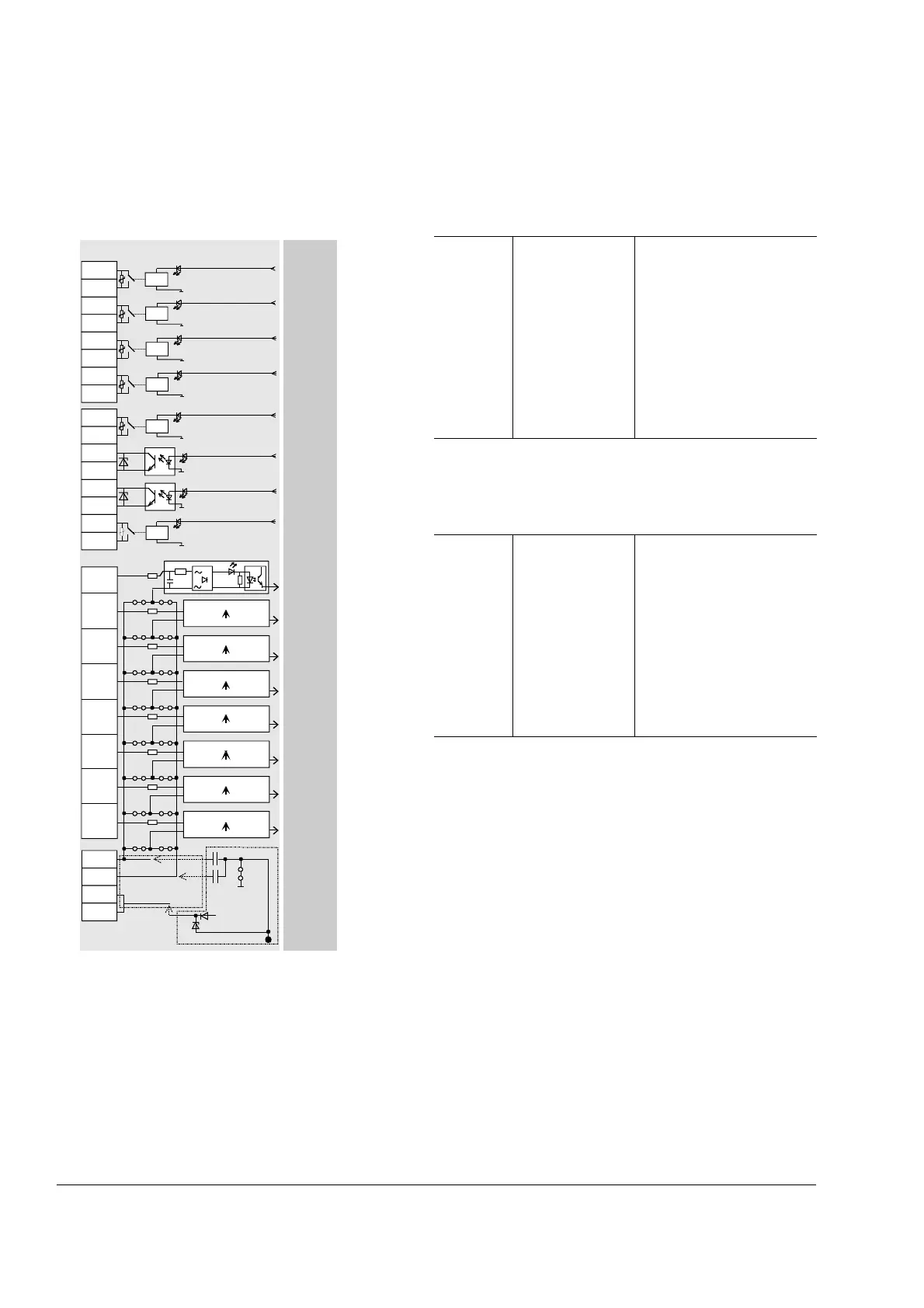
SDCS-IOB-2x
Software
+48V
100n
681
+
-
681
DIx
+
W2
W100
iob2x2_b.dsf
up to revision D
from
revision E on
conductive support
Note:
When the SDCS-CON-4 control board with the SDCS-IOB-
2 I/O board is installed, terminals X6: and X7: on the
SDCS-CON-4 must not be used.
X4:, X5: are screw-clamp terminal types for leads up to 4 mm² cross-
sectional area.
Default values are shown within the software diagrams.
The ground potential of the digital outputs may vary within ±100 V to
each other.
X6: / X7: are screw-clamp terminal types for leads up to 4 mm² cross-
sectional area
Input resistance: see diagram.
Input smoothing time constant: see diagram.
Smoothing time constant of channel 7 and 8 can be changed; see
fig. before.
Power supply for digital inputs X7:3,4:
• 48V / ≤ 50mA
• not galv. isolated from the DCS electronics!
• only available at SDCS-IOB-21
If the inputs are supplied from the internal +48 V (X7:3 and/or X7:4) a
connection must be done from either X7:1 and/or X7:2 to ground of
the DCS800 module. In default condition ground is identical to the
converter's frame.
If the inputs are supplied by any external source (+48 V DC, 115 V AC
or 230 V AC) the neutral line / - line must be connected to either X7:1
or X7:2. If the inputs should be controlled with the same voltage level,
but from two different voltage sources, having probably two different
ground levels, the first neutral line should be connected to X7:1 and
the second to X7:2. In this case the jumpers Wx connecting the inputs
to X7:2, but controlled by the source, connected to X7:1, must be cut
off.
The same method is needed for the other jumpers Wx.
High frequency grounding is done by 100 nF capacitor.
Output value Signal definition by Remarks
K1...K5, K8
K6, K7
Firmware
Firmware
potential-isolated by relays
(NO contact element)
Contact ratings:
AC: ≤ 250 V~/ ≤ 3 A~
DC: ≤ 24 V-/ ≤ 3 A-
or ≤ 115/230 V-/ ≤ 0.3 A-)
MOV-protected (275 V)
potential-isolated by optocoupler
Switching capacity: ≤ 50 mA
external voltage: ≤ 24 V-
Input value Signal definition by Remarks
Channel
1...8
IOB-21
0...8 V
18...60 V
IOB-22
0...20 V
60...130 V
IOB-23
0...40 V
90...250 V
Firmware
Firmware
potential-isolated by optocoupler
(24...48V-) R1...R8 = 4.7 kΩ
-> "0 signal"
-> "1 signal"
(115V~) R1...R8 = 22 kΩ
-> "0 signal"
-> "1 signal"
(230 V~) R1...R8 = 47 kΩ
-> "0 signal"
-> "1 sig."
including tolerance; absolute
max. values