Planning the electrical installation
48
3ADW000194R0611 DCS800 Hardware Manual f us
* 460 V < Supply < 600 V autotransformer strongly recommended, energy saving 20000 kWh/a
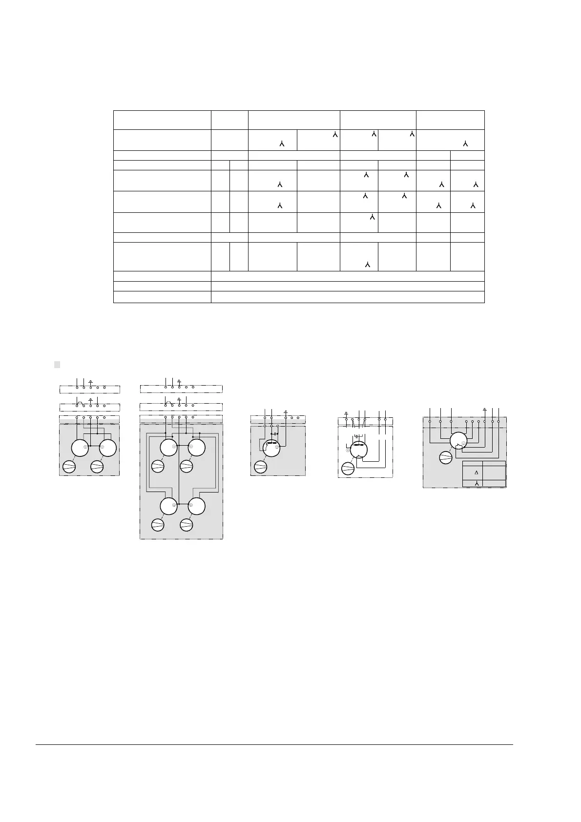
Fan connection for DCS800
Monitoring the DCS800 power section
a.The size D1...D5 power section is likewise monitored by an electrically isolated
PTC thermistor detector, which is installed on the heat sink in an isolated
configuration. Evaluation of the resistance and the protection effect correspond to
max. temperature of type code.
b.The size D6 and D7 power section isolated PTC thermistor is used for air entry
temperature. The detector thus measures the power section’s radiated heat and any
Fan
D2E 160 GR31M
380... 500 V
GR31M
525... 690 V
GR35C
400 / 690 V
Rated voltage [V] 230; 1~
400...450 Δ
450...500
400...500 Δ
500...690 500...690
500 Δ
400..460 Δ
600...690
Tolerance [%] ±10 ±10 ±10 +5/-10 ±10
Frequency [Hz] 50 60 50 60 50 60 50 60
Power consumption [W] 653 860
800 Δ
700
1340 Δ
800
1200
2900 Δ
2200
3600 Δ
3300
Current consumpt. [A] 2.50 3.4
1.45 Δ
0.91
2.0 Δ
0.9
1.2
6.5 Δ
2.3
4.9 Δ
3.0
Blocking current [A] 3.75 4.5
at 450 V Δ
8.5
at 500 V Δ
8.5
at 690 V
4.4
at 500 V Δ
8.5
at 400 V Δ
>25
at 400 V Δ
>30
Air flow [m3/h] freely blowing - - -
Air flow [m3/h]
at working point
800
2.5 A
750
3.2 A
1500
1.26 A
(450V Δ)
1600
1.6 A
(500V Δ)
1500
0.7 A
(690V
)
1600
1.65 A
(500V Δ)
4200
3.6 A
(400V Δ)
4250
4.1 A
(400V Δ)
Max. ambient temperature [° C] < 55
Useful lifetime of grease appr. 30000 h/40°
Protection
Temperatur detector: U
N
≤ 230 V~; I
N
≤ 2.5 A~
|-------------------------------------- Terminals on top of converter housing --------------------------------------|
Converter housing
Configuration 1
D1...D3
Configuration 2
D3
Configuration 3
D4
Configuration 4
D5
Configuration 5
D6, D7
12 3X2: 45
L
N
230 Vac
12 3X2: 45
L
N
115 Vac
M
~
12 3X2:
M
~
45
M55 M56
M
~
12 3X2:
M
~
45
M55 M56
M
~
M
~
M57 M58
12 3X2: 45
L
N
230 Vac
12 3X2: 45
L
N
115 Vac
M55
M
~
12 345X2:
LN
L
N
ϑ
either 230 Vac
or 115 Vac
M
~
ϑ
23156X2:
4
TW TW
LN
Fan_con_d.dsf
blue
black
brown
white
white
green /yellow
gray
gray
M
~
ϑ
U1 V1 W1 U2 V2 W2 TK TKPE
at
Connection
U1-W2
V1-U2
W1-V2
U2-V2-W2