Technical data
88
3ADW000194R0611 DCS800 Hardware Manual f us
➀ total smoothing time ≤ 2 ms
➁ -20...0...+20 mA by setting S1
➂ 4...20 mA by ➁ + Software function
➃ -1...0...-1 V by setting S2/S3 (CMR ±10 V)
-2...0...-2 mA by setting S2/S3 + S1 (CMR ±10 V)
➄ designated for PT100 evaluation per firmware and
hardware
➅ should always be used directly at SDCS-CON-4
X3:1...4
* short circuit proof
➆Residual current detection is selected as default. The jumpers S1:11-12 and S1:13-14 are set, inputs X3:9 and X3:10
and jumper S1:9-10 must not be used and inputs X3:11 and X3:12 serve as input for the current signal taken from a
current transformer. This detection is based on a sum current transformer where the secondary is connected through a
diode bridge to 100 Ohm resistor . Voltage will appear across the resistor, if the sum of the 3-phase current is not zero.
In case AI4 should be used for a different purpose, use the inputs/jumpers accordingly and take the block diagram as a
help.
Restrictions using jumper S1, S2 or S3:
The selection for the burden resistor across the input terminals can be done independent from S2 or S3 settings for inputs
AITAC, AI1, AI2, AI3 and AI4.
If the gain is set to 10 by using S2 or S3 and the 500 Ω burden resistor is activated, the input signal level is changed to -2
mA...0...+2 mA.
For input AI4 there are the following configurations available:
- input range ”20mA” , or
- input range ”10V”, or
- earth fault monitoring by Isum not equal to zero via X3:11 and X3:12
X2:
+10V
0V
-10V
AO1
AITAC
AO2
+/- I-act
AI4
10 ms
GND
0V
8 V = 325% [99.03]
max. 230% [4.05]
100k
1n
1n
100k
100k 100k
Power-
Source
Sense GND
Sense Power +
0V
AI2
3.3 ms
AI1
3.3 ms
-
+
-
+
-
+
-
+
500
S1
1
2
34
7
8
9
10
12
14
13
11
100
S1
x
R110
0V
0V
1.5 mA
5 mA
12
3
4
S5
S4
V17
4
5
7
X5:1
2
3
6
8
9
10
3
4
5
6
7
8
9
10
X4:1
2
11
12
8
7
4
X3:1
2
3
6
5
9
10
11
12
SDCS-IOB-3
Software
SDCS-CON-x
+
5
6
~
~
47.5
100
μ
100n
47.5
100
μ
100n
100μ
ChA +
ChA -
ChB +
ChB -
ChZ +
ChZ -
+24V
789
10
11 12
+24V
13
14
15
16
17 18
+24V456
S10
12 3
S10
AI3
10 ms
-
x10
S2
S3
x10
iob3x2_g.dsf
Note:
When the SDCS-CON-4 control board with the SDCS-IOB-3 I/O
board is installed, analogue tacho input at SDCS-CON-4 should
be used:
Terminals X3: (except for connector 1, 2, 3, 4), X4: and X5: on the
SDCS-CON-4 must not be used
.
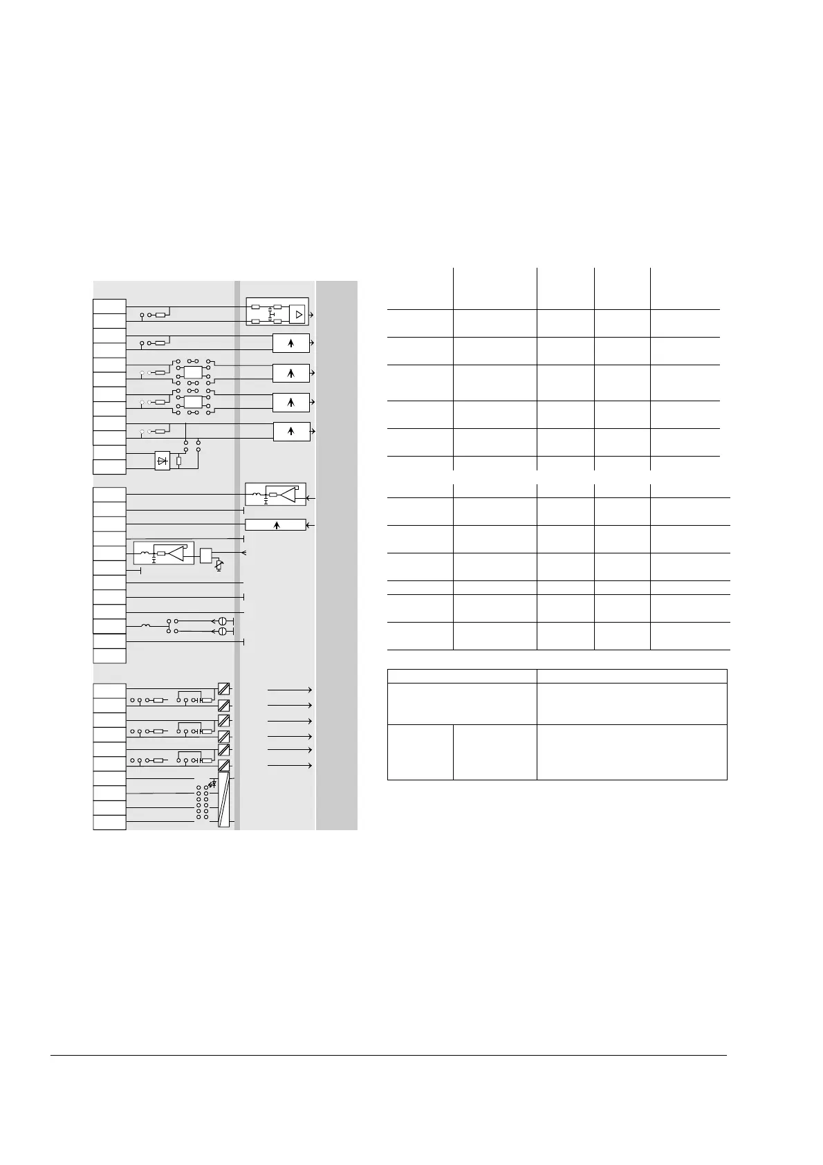
Resolution
[bit]
Input/output
values
Hardware
Scaling
by
Common
mode
range
Remarks
15 + sign -10...0...+10 V Firmware ±20 V ➀➁➂➅
15 + sign -10...0...+10 V Firmware ±20 V ➀➁➂
15 + sign -10...0...+10 V Firmware ±40 V ➀➁➂➃➄
15 + sign -10...0...+10 V Firmware ±40 V ➀➁➂➃➄
15 + sign -10...0...+10 V Firmware ±40 V ➀➁➂
➆
Power
11 + sign -10...0...+10 V Firmware ≤ 5 mA*
11 + sign -10...0...+10 V Firmware ≤ 5 mA*
analogue -10...0...+10 V R110 ≤ 5 mA* gain: 0.5...5
R
i
= 3 Ω≤ 5 mA* for external use
≤ 5 mA* e.g. reference
pot.
1.5 mA
5 mA
Curr. source for
PTC or PT100
Encoder supply Remarks
Inputs not isolated
Impedance = 120 Ω, if selected
max. frequence ≤ 300 kHz
5 V
12 V / 24 V
≤ 250 mA *
≤ 200 mA *
Sense lines for GND and supply to
correct voltage drops on cable (only if
5V/12V encoder is in use)