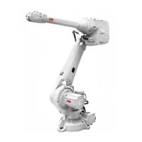
Required equipment - tools etc.
NoteArt. no.Equipment
For lubricating the o-ring.3HAB3537-1Grease
Always use removal tools in pairs.3HAC14631-1Removal tool, motor M12x
3HAC026061-001Lifting tool motor 2-3
Used to fix axis 3.3HAC12708-1Mechanical stop axis 3
M16x603HAB3409-86Attachment screws
For mechanical stop axis 3.
For mechanical stop axis 3.3HAA1001-186Washers
M10x1003HAC15521-1Guide pins
For guiding the motor.
M10x1503HAC15521-2Guide pins
For guiding the motor.
300 mm3HAC12342-1Extension for bits 1/2"
Used to rotate the motor pinion when
mating it to the gear when brakes are
released with the 24 VDC power sup-
ply.
3HAC17105-1Rotation tool
24 VDC max 1.5 A-Power supply
For releasing the brakes.
Content is defined in section Standard
tools on page 465.
-Standard toolkit
Complete kit which also includes user
manual.
3HAC15716-1Calibration Pendulum toolkit
These procedures include references
to the tools required.
Other tools and procedures
may be required. See refer-
ences to these procedures in
the step-by-step instructions
below.
See Circuit dia-
gram.
Circuit diagram
Additional equipment - Foundry Prime
NoteArt. no.Equipment
Mercasol3HAC034903-001Rust preventive
3HAC026759-001Sikaflex 521FC
12340011-116Loctite 574
CAUTION
Always cut the paint with a knife and grind the paint edge when disassembling
parts. See Cut the paint or surface on the robot before replacing parts on page 219.
Continues on next page
Product manual - IRB 6640 Foundry Prime 355
3HAC040586-001 Revision: N
© Copyright 2011-2018 ABB. All rights reserved.
4 Repair
4.6.3 Replacing motor axis 3
Continued

 Loading...


